Rear Drive Shaft Assembly -- Reassembly |
- HINT:
- Use the same procedures for the RH side and LH side.
- The procedures listed below are for the LH side.
| 1. INSTALL REAR DRIVE SHAFT DUST COVER LH |
 |
Using SST and a press, press in a new drive shaft dust cover.
- SST
- 09527-10011
- NOTICE:
- The dust cover should be installed completely.
- Be careful not to damage the dust cover.
| 2. INSTALL REAR DRIVE SHAFT INBOARD JOINT SHAFT SNAP RING LH |
Install a new hole snap ring.
| 3. INSTALL REAR DRIVE SHAFT INBOARD JOINT ASSEMBLY LH |
Wrap the spline of the outboard joint shaft with vinyl tape to prevent the boots from being damaged.
Install new parts to the outboard joint shaft in the following order.
Inboard joint boot clamp
No. 2 inboard joint boot clamp
Inboard joint boot
Place the beveled side of the tripod axial spline toward the outboard joint.
Align the matchmarks placed before removal.
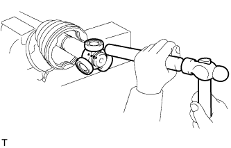
Using a brass bar and hammer, tap the tripod joint onto the drive shaft.
- NOTICE:
- Do not tap the rollers.
- Be sure to install the tripod joint in the correct direction.
 |
Pack the inboard joint shaft and boot with grease from the boot kit.
- Standard grease capacity:
- 86 to 96 g (3.0 to 3.4 oz.)
Using a snap ring expander, install a new shaft snap ring.
 |
Align the matchmarks, and install the inboard joint to the outboard joint shaft.
| 4. INSTALL REAR AXLE INBOARD JOINT BOOT |
Install the inboard joint boot to the inboard joint.
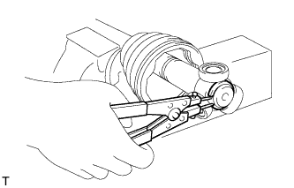
| 5. INSTALL REAR DRIVE SHAFT INBOARD JOINT BOOT NO. 2 CLAMP LH |
 |
Using needle-nose pliers, install the No. 2 inboard joint boot clamp, as shown in the illustration.
- NOTICE:
- Be careful not to damage the boot.
| 6. INSTALL REAR DRIVE SHAFT INBOARD JOINT BOOT CLAMP LH |
Using a screwdriver, install the inboard joint boot clamp, as shown in the illustration.
- NOTICE:
- Be careful not to damage the boot.
 |
| 7. INSPECT REAR DRIVE SHAFT |
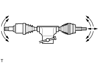 |
Check that there is no severe play in the radial direction of the outboard joint.
Check that the inboard joint slides smoothly in the thrust direction.
Check that there is no severe play in the radial direction of the inboard joint.
Check the boots for damage.
- NOTICE:
- Keep the drive shaft assembly level during inspection.
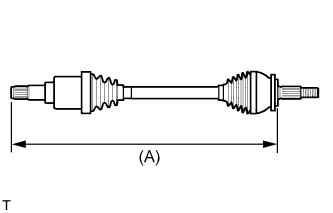
- HINT:
- For dimension (A), refer to the following values.
- Reference value:
- 733.8 mm (28.890 in.)
 |