Front Drive Shaft Assembly (For 4Wd) -- Reassembly |
| 1. INSTALL FRONT DRIVE SHAFT BEARING |
 |
Install a new snap ring to the inboard shaft.
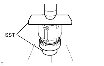
Using SST and a press, press the drive shaft bearing onto the inboard joint RH.
- SST
- 09527-10011
09710-04081
- NOTICE:
- Make sure the bearing is completely installed.
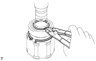
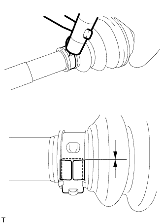
Using a snap ring expander, install a new snap ring.
 |
| 2. INSTALL FRONT DRIVE SHAFT DUST COVER RH |
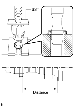 |
Using SST and a press, press a new drive shaft dust cover onto the inboard joint until the distance shown in the illustration reaches the specification.
- SST
- 09527-10011
- Standard distance:
- 104 +/-0.5 mm (4.09 +/-0.02 in.)
- NOTICE:
- Be careful not to damage the dust cover.
| 3. INSTALL FRONT DRIVE SHAFT DUST COVER LH |
 |
Using SST and a press, press a new drive shaft dust cover onto the inboard joint.
- SST
- 09527-10011
- NOTICE:
- Make sure the dust cover is installed so that the inboard joint contacts the dust cover at the location indicated by the arrows in the illustration.
- Be careful not to damage the dust cover.
| 4. INSTALL FRONT DRIVE SHAFT HOLE SNAP RING LH |
Install a new hole snap ring.
| 5. INSTALL FRONT AXLE OUTBOARD JOINT BOOT |
 |
- HINT:
- Before installing the boots, wrap the splines of the shaft with vinyl tape to prevent the boots from being damaged.
Temporarily install a new outboard joint boot No. 2 clamp to the outboard joint shaft.
Install a new outboard joint boot so that it is between the outboard joint boot No. 2 clamp and outboard joint shaft.
Temporarily install a new outboard joint boot clamp to the outboard joint boot.
Pack the outboard joint shaft and boot with grease from the boot kit.
- Standard grease capacity:
Item Specified Condition 1AZ-FE, 2AZ-FE for U140F
3ZR-FAE for K111F190 to 200 g (6.7 to 7.1 oz.) 1AZ-FE, 2AZ-FE for E352F/E359F
2GR-FE
3ZR-FAE for EB61F205 to 215 g (7.2 to 7.6 oz.)
| 6. TIGHTEN FRONT AXLE OUTBOARD JOINT BOOT NO. 2 CLAMP LH |
 |
- CAUTION:
- Wear protective gloves while performing the operation and be careful to avoid cutting your hands or other body parts.
Install a new boot clamp to the outboard joint boot and temporarily bend the lever.
- NOTICE:
- When temporarily bending the lever, make sure not to deform the band and lever.
- Set the clamp correctly in the guide groove and align it with the interior of the vehicle as much as possible.
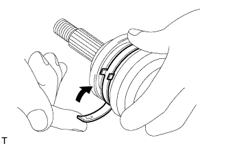
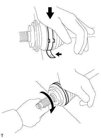
With the joint on the working surface, use your body weight to press down on the joint with one hand. Then, roll the joint forward, as shown in the illustration, and press the lever in until a "click" sound is heard.
- NOTICE:
- Do not damage the deflector.
- Make sure the joint is in full contact with the working surface at all times.
 |
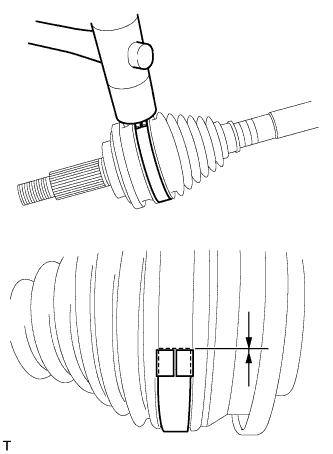
Using a plastic-faced hammer, bend the tabs of the buckle to fix the lever in place. At the same time, use the plastic-faced hammer to adjust the position of the lever so that the end of the lever is aligned with the edge of the buckle.
- NOTICE:
- Do not strike the shaft forcefully with the plastic-faced hammer.
 |
| 7. TIGHTEN FRONT AXLE OUTBOARD JOINT BOOT NO. 2 CLAMP RH |
- HINT:
- Use the same procedures described for the LH side.
| 8. TIGHTEN FRONT AXLE OUTBOARD JOINT BOOT CLAMP LH |
 |
- CAUTION:
- Wear protective gloves while performing the operation and be careful to avoid cutting your hands or other body parts.
Install a new boot clamp to the outboard joint boot and temporarily bend the lever.
- NOTICE:
- When temporarily bending the lever, make sure not to deform the band and lever.
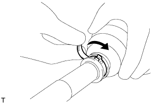
Using water pump pliers, temporarily lock the boot clamp by bending the lever down until a "click" sound is heard.
 |
Using a plastic-faced hammer, bend the tabs of the buckle to fix the lever in place. At the same time, use the plastic-faced hammer to adjust the position of the lever so that the end of the lever is aligned with the edge of the buckle.
- NOTICE:
- Do not strike the shaft forcefully with the plasticfaced hammer.
 |
| 9. TIGHTEN FRONT AXLE OUTBOARD JOINT BOOT CLAMP RH |
- HINT:
- Use the same procedures described for the LH side.
| 10. INSTALL FRONT DRIVE SHAFT DAMPER LH (except E352F/E359F, EB61F) |
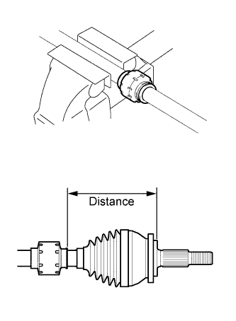 |
Secure the shaft in a vise between aluminum plates.
Temporarily install a new drive shaft damper clamp to the shaft, and then install the drive shaft damper so that it is between the damper clamp and the shaft.
- HINT:
- Make sure the damper clamp is on the outboard joint side.
Adjust the position of the drive shaft damper so that the distance shown in the illustration is within the specified range.
- Standard distance:
- 161 to 165 mm (6.339 to 6.496 in.)
| 11. TIGHTEN FRONT DRIVE SHAFT DAMPER CLAMP |
 |
Secure the shaft in a vise between aluminum plates.
Tighten the drive shaft damper clamp.
- NOTICE:
- Make sure the clamp is installed in the correct position.
for One Touch Type Clamp:
Using a screwdriver, tighten the drive shaft damper clamp, as shown in the illustration.
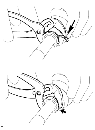
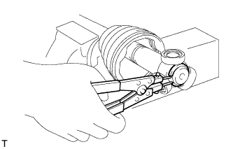
for Claw Engagement Type Clamp:
Using needle-nose pliers, tighten the drive shaft damper clamp, as shown in the illustration.
| 12. INSTALL FRONT DRIVE SHAFT DAMPER |
 |
Secure the shaft in a vise between aluminum plates.
Temporarily install a new drive shaft damper clamp to the shaft, and then install the drive shaft damper so that it is between the damper clamp and the shaft.
- HINT:
- Make sure the damper clamp is on the outboard joint side.
Adjust the position of the drive shaft damper so that the distance shown in the illustration is within the specified range.
- Standard distance:
- 161 to 165 mm (6.339 to 6.496 in.)
| 13. TIGHTEN FRONT DRIVE SHAFT DAMPER CLAMP |
- HINT:
- Use the same procedures described for the LH side.
| 14. INSTALL FRONT DRIVE INBOARD JOINT ASSEMBLY LH |
- HINT:
- Before installing the boots, wrap the splines of the shaft with vinyl tape to prevent the boots from being damaged.
Wrap the spline of the outboard joint shaft with vinyl tape to prevent the boots from being damaged.
Install new parts to the outboard joint shaft in the following order.
Inboard joint boot clamp
No. 2 inboard joint boot clamp
Inboard joint boot
Place the beveled side of the tripod axial spline toward the outboard joint.
 |
Align the matchmarks placed before removal.
Using a brass bar and hammer, tap the tripod onto the shaft.
- NOTICE:
- Do not tap the rollers.
- Be sure to install the tripod in the correct direction.
Pack the inboard joint shaft and boot with grease from the boot kit.
- Standard grease capacity:
- 175 to 185 g (6.2 to 6.5 oz.)
Using a snap ring expander, install a new shaft snap ring.
 |
Align the matchmarks, and install the inboard joint to the outboard joint shaft.
| 15. INSTALL FRONT DRIVE INBOARD JOINT ASSEMBLY RH |
- HINT:
- Use the same procedures described for the LH side.
| 16. INSTALL FRONT AXLE INBOARD JOINT BOOT |
Install the inboard joint boot to the inboard joint.
| 17. TIGHTEN FRONT AXLE INBOARD JOINT BOOT CLAMP LH |
 |
for One Touch Type Clamp:
Using a screwdriver, tighten the inboard joint boot clamp, as shown in the illustration.- NOTICE:
- Be careful not to damage the boot.
for Claw Engagement Type Clamp:
Using needle-nose pliers, tighten the inboard joint boot clamp, as shown in the illustration.- NOTICE:
- Be careful not to damage the boot.
| 18. TIGHTEN FRONT AXLE INBOARD JOINT BOOT CLAMP RH |
- HINT:
- Use the same procedures described for the LH side.
| 19. TIGHTEN FRONT AXLE INBOARD JOINT BOOT NO. 2 CLAMP LH |
 |
for One Touch Type Clamp:
Using a screwdriver, tighten the No. 2 inboard joint boot clamp, as shown in the illustration.- NOTICE:
- Be careful not to damage the boot.
for Claw Engagement Type Clamp:
Using needle-nose pliers, tighten the No. 2 inboard joint boot clamp, as shown in the illustration.- NOTICE:
- NOTICE: Be careful not to damage the boot.
| 20. TIGHTEN FRONT AXLE INBOARD JOINT BOOT NO. 2 CLAMP RH |
- HINT:
- Use the same procedures described for the LH side.
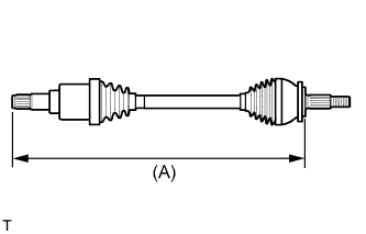
| 21. INSPECT FRONT DRIVE SHAFT |
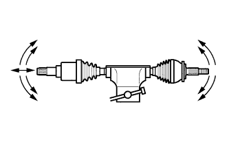 |
Secure the shaft in a vise between aluminum plates.
Check that there is no severe play in the radial direction of the outboard joint.
Check that the inboard joint slides smoothly in the thrust direction.
Check that there is no severe play in the radial direction of the inboard joint.
Check the boots for damage.
Measure length (A) of the drive shaft.
- NOTICE:
- Keep the drive shaft assembly level during inspection.
- Standard (Reference):
Item Drive shaft LH (Dimension) Drive shaft RH (Dimension) 1AZ-FE, 2AZ-FE for U140F 572.5 mm (1.88 ft.) 918 mm (3.01 ft.) 1AZ-FE, 2AZ-FE for E352E/E359 583.6 mm (1.91 ft.) 909.4 mm (2.98 ft.) 2GR-FE 570.9 mm (1.87 ft.) 922.4 mm (3.03 ft.) 3ZR-FAE for EB61F 594.6 mm (1.95 ft.) 896.4 mm (2.94 ft.) 3ZR-FAE for K111F 591.2 mm (1.94 ft.) 881.9 mm (2.89 ft.)
 |