Continuously Variable Transaxle Assembly -- Installation |
| 1. INSPECT TORQUE CONVERTER ASSEMBLY |
Inspect the one-way clutch.
Press on the splines of the stator with a finger and rotate it. Check that it rotates smoothly when turned clockwise and rotates with difficulty when turned counterclockwise.
If necessary, clean the converter and recheck the one-way clutch.
Replace the converter if the one-way clutch still fails the inspection.
 |
Determine the condition of the torque converter clutch assembly.
If the inspection result of the torque converter clutch assembly satisfies the following conditions, replace the torque converter clutch assembly.
Malfunction:- A metallic sound is emitted from the torque converter clutch assembly during the stall test or when the shift lever is moved to N.
- The one-way clutch is free or locked in both directions.
- The amount of powder in the fluid is more than the sample shown in the illustration.
- HINT:
- The sample shows approximately 0.025 liters (0.026 US qts, 0.022 Imp. qts) of fluid that is taken out from the removed torque converter clutch.
- A metallic sound is emitted from the torque converter clutch assembly during the stall test or when the shift lever is moved to N.
 |
Replace the fluid in the torque converter clutch.
If the fluid is discolored and/or has a foul odor, stir the fluid in the torque converter clutch and drain it.
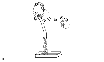
Clean and check the oil cooler and oil pipe line.
If the torque converter is inspected or the fluid is changed, clean the oil cooler and oil pipe line.
- HINT:
- Apply compressed air at 196 kPa (2 kgf/cm2, 28 psi) into the inlet hose.
- If an excessive amount of fine powder is found in the fluid, add new fluid using a bucket pump and clean the oil cooler and oil pipe line again.
- NOTICE:
- When inserting the air gun into the inlet hose, be sure not to damage the inside of the hose.
If the fluid is cloudy, inspect the oil cooler.
Prevent deformation of the torque converter clutch and damage to the oil pump gear.
When there is any damage to the end of the bolt for the torque converter and to the bottom of the bolt hole, replace the bolt and torque converter.
Make sure all of the bolts are the same length.
Bolts with washers must be used.
 |
| 2. INSTALL CVT OIL PUMP TYPE T OIL SEAL |
Ensure that there is no dirt or foreign matter on your hands, and then apply genuine TOYOTA MP grease No.2 to the entire periphery of the lip of a new CVT oil pump type T oil seal.
Temporarily attach the CVT oil pump type T oil seal by pressing it onto the installation surface of the oil pump housing manually.
Clean the oil seal contact section of the SST and the area around it.
 |
Using the SST, drive the CVT oil pump type T oil seal in evenly, as far as the side surface of the oil pump housing.
- SST
- 09309-36010
- NOTICE:
- Drive the oil seal in gradually, while visually checking the parallelism.
- After the installation, confirm that the oil seal has been driven in as far as the side surface of the oil pump housing.
- Wipe off any grease that has oozed out with your hand.
- HINT:
- The oil seal should be driven in between 0 and 0.5mm (as measured from the side surface of the oil pump housing).
| 3. INSTALL TORQUE CONVERTER ASSEMBLY |
Clean the torque converter set bolt holes.
Using a vernier caliper and straightedge, measure dimension "A" between the transaxle fitting surface of the engine*1 and the torque converter fitting surface of the drive plate*2. (#)
 |
Turn the front oil pump drive gear so that the groove is at the top and put a matchmark on the housing.
Text in Illustration *1 Matchmark *2 Groove
 |
Put a matchmark on the torque converter so that the position of its key is clearly indicated.
Text in Illustration *1 Key *2 Matchmark
 |
Align the matchmark on the housing with the one on the torque converter and mesh the splines of the input shaft with the turbine runner splines.
Text in Illustration *1 Matchmark - NOTICE:
- Install the torque converter horizontally to the input shaft.
 |
Rotate the torque converter and mesh the splines of the stator shaft with the stator splines.
Text in Illustration *1 Matchmark *2 Oil Seal - HINT:
- Rotate the torque converter approximately 180°.
- NOTICE:
- Do not damage the oil seal.
- Install the torque converter horizontally to the input shaft.
 |
Rotate the torque converter again, align the matchmark on the housing with the one on the torque converter and insert the key of the torque converter into the groove of the oil pump drive gear.
Text in Illustration *1 Matchmark *2 Oil Seal - NOTICE:
- Do not push the torque converter excessively when rotating it.
- Do not damage the oil seal.
- Install the torque converter horizontally to the input shaft.
 |
Using a vernier caliper and straightedge, measure dimension "B" shown in the illustration and check that dimension "B" is more than dimension "A" (which was measured in step (#)).
- Standard:
- A + 1 mm (0.0394 in.) or more
- NOTICE:
- Subtract the thickness of the straightedge from the measured value to gain dimension "B".
 |
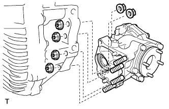
| 4. INSTALL WIRE HARNESS CLAMP BRACKET |
Install the 4 wire harness clamp brackets to the continuously variable transaxle with the 4 bolts.
- Torque:
- 7.7 N*m{78 kgf*cm, 68 in.*lbf}
| 5. INSTALL NO. 1 TRANSMISSION CONTROL CABLE BRACKET |
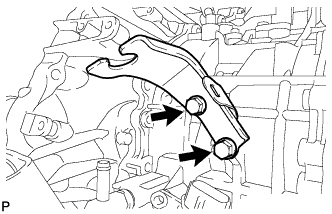 |
Install the No. 1 transmission control cable bracket to the continuously variable transaxle with the 2 bolts.
- Torque:
- 12 N*m{122 kgf*cm, 9 ft.*lbf}
| 6. INSTALL TRANSFER ASSEMBLY |
except K111F:
Install the transfer to the transaxle with the 6 nuts and 2 bolts.- Torque:
- 69 N*m{700 kgf*cm, 51 ft.*lbf}
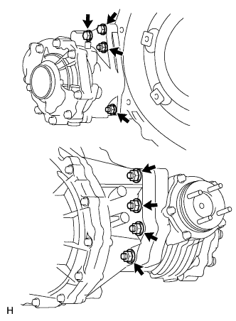 |
for K111F:
Install the transfer to the transaxle with the 6 nuts and 2 bolts.- Torque:
- 69 N*m{700 kgf*cm, 51 ft.*lbf}
 |
| 7. INSTALL CONTINUOUSLY VARIABLE TRANSAXLE ASSEMBLY |
 |
Apply clutch spline grease to the surface of the torque converter centerpiece that contacts the crankshaft.
- Clutch spline grease:
- Toyota Genuine Clutch Spline Grease or equivalent
- Maximum grease amount:
- Approximately 1 g (0.0353 oz.)
Text in Illustration *1 Torque Converter Centerpiece *2 Crankshaft
Confirm that the 2 knock pins are on the transaxle contact surface of the engine block before transaxle installation.
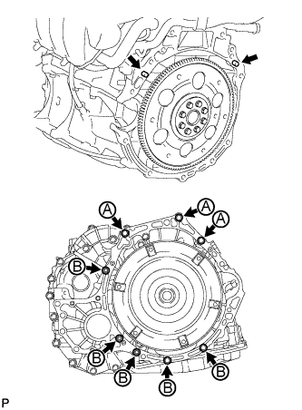 |
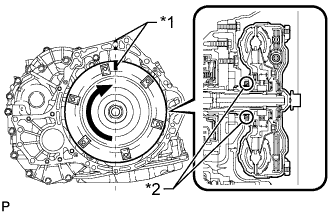
Maintain the engine and continuously variable transaxle assembly in a horizontal position, align the knock pins with each hole on the continuously variable transaxle assembly and install the continuously variable transaxle assembly with the 8 bolts shown in the illustration.
- Torque:
- for bolt A:
- 38 N*m{387 kgf*cm, 28 ft.*lbf}
- for bolt B:
- 40 N*m{408 kgf*cm, 30 ft.*lbf}
- HINT:
- Bolt A: Install from the transaxle side.
- Bolt B: Install from the engine side.
- CAUTION:
- Make sure that the torque converter rotates.
| 8. INSTALL DRIVE PLATE AND TORQUE CONVERTER SETTING BOLT |
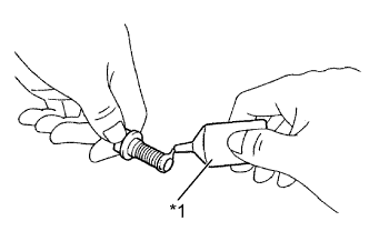 |
Apply a few drops of adhesive to 2 or 3 threads of the tips of the 6 torque converter setting bolts.
- Adhesive:
- Toyota Genuine Adhesive 1324,
Three Bond 1324 or equivalent
Text in Illustration *1 Adhesive
Turn the crankshaft to gain access to the installation locations of the 6 torque converter setting bolts and install each bolt while holding the crankshaft pulley bolt with a wrench.
- Torque:
- 41 N*m{418 kgf*cm, 30 ft.*lbf}
- NOTICE:
- Install the black bolt first, and then the 5 silver bolts.
 |
Install the flywheel housing under cover.
| 9. INSTALL ENGINE WIRE |
for Front Side:
Attach the 3 wire harness clamps and connect the 3 revolution sensor connectors, park/neutral position sensor connector and transmission wire connector to the continuously variable transaxle.
for Rear Side:
Attach the 2 wire harness clamps and connect the oil pressure sensor connector to the continuously variable transaxle.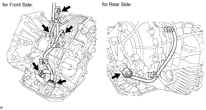
| 10. INSTALL GROUND CABLE |
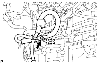 |
Install the ground cable to the continuously variable transaxle with the bolt and attach the clamp.
- Torque:
- 8.4 N*m{85 kgf*cm, 74 in.*lbf}
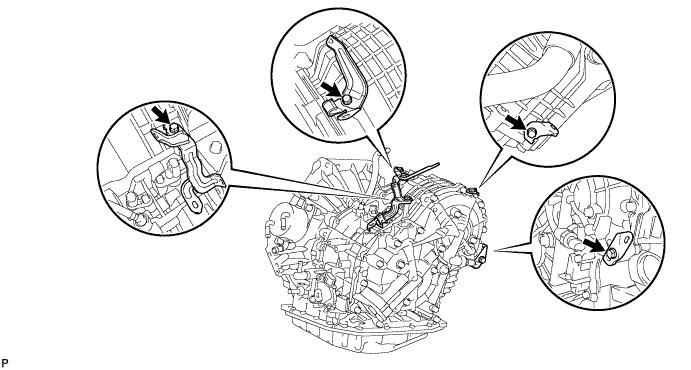
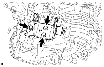
| 11. INSTALL REAR ENGINE MOUNTING BRACKET |
 |
Install the rear engine mounting bracket to the continuously variable transaxle with the 3 bolts.
- Torque:
- 45 N*m{459 kgf*cm, 33 ft.*lbf}
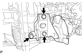
| 12. INSTALL FRONT ENGINE MOUNTING BRACKET |
 |
Install the front engine mounting bracket to the continuously variable transaxle with the 3 bolts.
- Torque:
- 64 N*m{653 kgf*cm, 47 ft.*lbf}
| 13. INSTALL ENGINE MOUNTING BRACKET LH |
 |
Install the engine mounting bracket LH to the continuously variable transaxle with the 3 bolts.
- Torque:
- 64 N*m{653 kgf*cm, 47 ft.*lbf}
| 14. INSTALL STARTER ASSEMBLY |
Install the starter with the 2 bolts.
- Torque:
- 37 N*m{380 kgf*cm, 27 ft.*lbf}
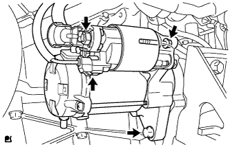 |
Connect the starter connector.
Connect starter wire with the nut.
- Torque:
- 9.8 N*m{100 kgf*cm, 87 in.*lbf}
Connect the terminal cap.
| 15. INSTALL OIL COOLER |
 |
Install the oil cooler to the continuously variable transaxle with the 3 bolts.
- Torque:
- 12 N*m{117 kgf*cm, 8 ft.*lbf}
Connect the 2 oil cooler hoses to the continuously variable transaxle.
- NOTICE:
- Make sure the paint marks and pinching portion of each clip are facing the directions shown in the illustration.
Text in Illustration *1 White Paint Mark
| 16. CONNECT WATER BY-PASS HOSE |
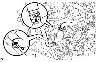 |
Connect the 2 water by-pass hoses to the oil cooler.
- NOTICE:
- Make sure the pinching portion of each clip is facing the directions shown in the illustration and the paint marks are aligned as shown in the illustration.
Text in Illustration *1 Yellow Paint Mark
| 17. INSTALL ENGINE ASSEMBLY WITH TRANSAXLE |
Install the engine with transaxle (RAV4_ACA30 RM000003PXK007X.html).
| 18. RESET MEMORY |
Perform Reset Memory (CVT initialization) when replacing the continuously variable transaxle assembly (RAV4_ACA30 RM000003UQR00VX.html).