Continuously Variable Transaxle System Pattern Select Switch Sport Mode Circuit
K111F Cvt. Toyota Rav4. Aca30, 33, 38 Gsa33 Zsa30, 35
DESCRIPTION
WIRING DIAGRAM
INSPECTION PROCEDURE
INSPECT NO. 1 PATTERN SELECT SWITCH ASSEMBLY
CHECK HARNESS AND CONNECTOR (NO. 1 PATTERN SELECT SWITCH ASSEMBLY - BODY GROUND)
CHECK HARNESS AND CONNECTOR (NO. 1 PATTERN SELECT SWITCH ASSEMBLY - ECM)
REPLACE ECM
PERFORM INITIALIZATION
CONTINUOUSLY VARIABLE TRANSAXLE SYSTEM - Pattern Select Switch Sport Mode Circuit |
DESCRIPTION
The ECM memory contains the programs for the normal and sport shift patterns.By following the programs corresponding to the signals from the No. 1 pattern select switch assembly, the park/neutral position switch and other various sensors, the ECM switches the shift control solenoid valves on and off, and controls the transaxle gear ratio.
WIRING DIAGRAM
INSPECTION PROCEDURE
| 1.INSPECT NO. 1 PATTERN SELECT SWITCH ASSEMBLY |
Remove the No. 1 pattern select switch assembly.
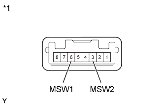
Measure the resistance according to the value(s) in the table below.
- Standard Resistance:
Tester Connection
| Switch Condition
| Specified Condition
|
6 (MSW1) - 3 (MSW2)
| Pattern select switch on
| Below 1 Ω
|
6 (MSW1) - 3 (MSW2)
| Pattern select switch off
| 10 kΩ or higher
|
Text in Illustration*1
| Component without harness connected
(No. 1 Pattern Select Switch Assembly)
|
| | REPLACE NO. 1 PATTERN SELECT SWITCH ASSEMBLY |
|
|
| 2.CHECK HARNESS AND CONNECTOR (NO. 1 PATTERN SELECT SWITCH ASSEMBLY - BODY GROUND) |
Disconnect the No. 1 pattern select switch assembly connector.
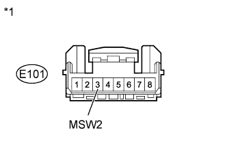
Measure the resistance according to the value(s) in the table below.
- Standard Resistance:
Tester Connection
| Condition
| Specified Condition
|
E101-3 (MSW2) - Body ground
| Always
| Below 1 Ω
|
Text in Illustration*1
| Front view of wire harness connector
(to No. 1 Pattern Select Switch Assembly)
|
| | REPAIR OR REPLACE HARNESS OR CONNECTOR |
|
|
| 3.CHECK HARNESS AND CONNECTOR (NO. 1 PATTERN SELECT SWITCH ASSEMBLY - ECM) |
Disconnect the ECM connector.
Measure the resistance according to the value(s) in the table below.
- Standard Resistance:
Tester Connection
| Switch Condition
| Specified Condition
|
A12-17 (PWMS) - Body ground
| Pattern select switch on
| Below 1 Ω
|
A12-17 (PWMS) - Body ground
| Pattern select switch off
| 10 kΩ or higher
|
Text in Illustration*1
| Front view of wire harness connector
(to ECM)
|
| | REPAIR OR REPLACE HARNESS OR CONNECTOR |
|
|
Replace the ECM (RAV4_ACA30 RM0000017UO01KX.html).
- NOTICE:
- Performing reset memory will clear the learned values of both the yaw rate sensor assembly*1 or deceleration sensor*2 (deceleration sensor 0 point calibration) and CVT oil pressure (CVT oil pressure calibration). Make sure to perform reset memory, yaw rate sensor assembly*1 or deceleration sensor*2 0 point calibration and CVT oil pressure calibration when replacing any of the parts shown in the following table:
Replaced Part
|
- Continuously variable transaxle assembly
- ECM
- Oil pressure sensor
- Yaw rate sensor assembly (w/ VSC)
- Deceleration sensor (w/o VSC)
- Brake actuator assembly (skid control ECU)
|
- After performing reset memory, always perform yaw rate sensor assembly*1 or deceleration sensor*2 (deceleration sensor 0 point) calibration first, and then CVT oil pressure calibration.
- Always perform 0 point calibration with the vehicle on level ground.
- Do not shake or vibrate the vehicle during 0 point calibration.
Using the intelligent tester, perform reset memory, deceleration sensor 0 point calibration and CVT oil pressure calibration (RAV4_ACA30 RM000003UQR002X.html).
Check that no DTC is stored.