Dtc B2276 Accr Signal Circuit Malfunction
Lexus IS250 IS220d GSE20 ALE20 2AD-FHV STARTING
DESCRIPTION
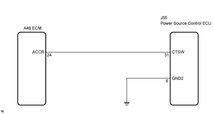
WIRING DIAGRAM
INSPECTION PROCEDURE
CHECK CONNECTORS
CHECK WIRE HARNESS (POWER SOURCE CONTROL ECU - BODY GROUND)
CHECK WIRE HARNESS (POWER SOURCE CONTROL ECU - ECM)
INSPECT ECM
INSPECT POWER SOURCE CONTROL ECU
DTC B2276 ACCR Signal Circuit Malfunction
DESCRIPTION
This DTC is output when the ACCR output circuits inside the power source control ECU are open or short.
- When the power source control ECU is replaced with a new one and the negative (-) battery terminal is connected, the power source mode becomes the IG-ON mode. When the battery is removed and reinstalled, the power source mode that was selected when the battery was removed is restored.
| DTC No. | DTC Detection Condition | Trouble Area |
| B2276 |
ACCR output circuit inside power source control ECU or other related circuit is malfunctioning |
Power source control ECU
ECM
Wire harness or connector
|
WIRING DIAGRAM
INSPECTION PROCEDURE
Check that the connectors are securely connected and the terminals are not deformed or loose.
- OK:
- The connectors are securely connected and the terminals are not deformed or loose.
| | REPAIR OR REPLACE CONNECTORS |
|
|
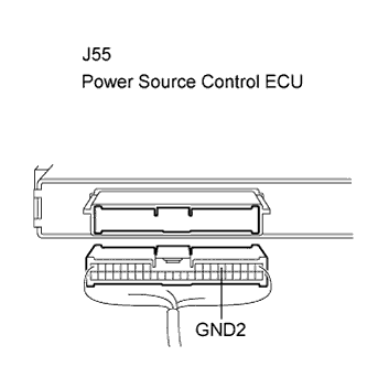
| 2.CHECK WIRE HARNESS (POWER SOURCE CONTROL ECU - BODY GROUND) |
Disconnect the J55 ECU connector.
Measure the resistance according to the value(s) in the table below.
- Standard resistance:
| Tester Connection (Symbols) | Condition | Specified Condition |
| J55-6 (GND2) - Body ground | Always | Below 1 Ω |
| | REPAIR OR REPLACE HARNESS OR CONNECTOR |
|
|
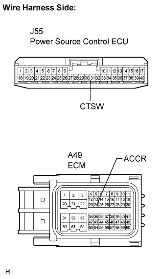
| 3.CHECK WIRE HARNESS (POWER SOURCE CONTROL ECU - ECM) |
Disconnect the A49 ECM connector.
Measure the resistance according to the value(s) in the table below.
- Standard resistance:
| Tester Connection (Symbols) | Condition | Specified Condition |
| J55-31 (CTSW) - A49-24 (ACCR) | Always | Below 1 Ω |
| J55-31 (CTSW) or A49-24 (ACCR) - Body ground | Always | 10 kΩ or higher |
| | REPAIR OR REPLACE HARNESS OR CONNECTOR |
|
|
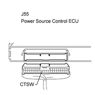
Reconnect the A49 ECM connector.
Measure the voltage according to the value(s) in the table below.
- Standard voltage:
| Tester Connection (Symbols) | Condition | Specified Condition |
| J55-31 (CTSW) - Body ground | Always | 8 to 14 V |
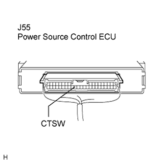
| 5.INSPECT POWER SOURCE CONTROL ECU |
Reconnect the J55 ECU connector.
Measure the voltage according to the value(s) in the table below.
- Standard voltage:
| Terminal No. (Symbol) | Condition | Specified condition |
| J55-31 (CTSW) - Body ground | Clutch pedal depressed, Engine switch on (ST) → on (IG) | 0.1 to 0.8 V (*1) →
Output voltage at terminal AM2 is -2 V or more. |
- *1: Voltage is output only when the engine is cranking.
| | REPLACE POWER SOURCE CONTROL ECU |
|
|
| OK | |
| |
| CHECK INTERMITTENT PROBLEMS |
|