Manual Transaxle Unit Reassembly
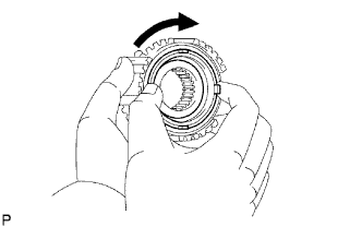
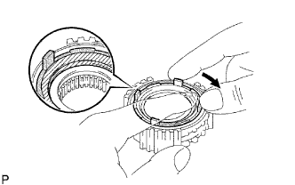
INSTALL SYNCHRONIZER PULL RING
INSTALL NO. 5 SYNCHRONIZER RING MIDDLE
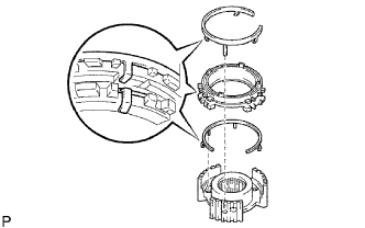
INSTALL NO. 3 SYNCHROMESH SHIFTING KEY SPRING
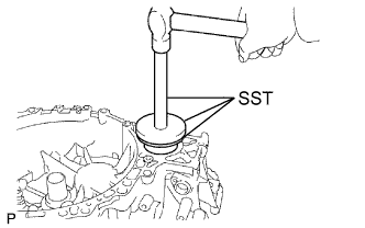
INSTALL FRONT TRANSAXLE CASE COVER OIL SEAL
INSTALL FRONT DIFFERENTIAL CASE FRONT TAPERED ROLLER BEARING
INSTALL FRONT DIFFERENTIAL CASE REAR TAPERED ROLLER BEARING
INSTALL TRANSAXLE CASE OIL SEAL
INSTALL REAR OUTPUT SHAFT BEARING
INSTALL OUTPUT SHAFT COVER
INSTALL FRONT OUTPUT SHAFT BEARING
ADJUST OUTPUT SHAFT BEARING PRELOAD
ADJUST TAPERED ROLLER BEARING PRELOAD
INSTALL FRONT TRANSAXLE CASE OIL SEAL
INSTALL FRONT INPUT SHAFT BEARING
INSTALL MANUAL TRANSAXLE CASE RECEIVER
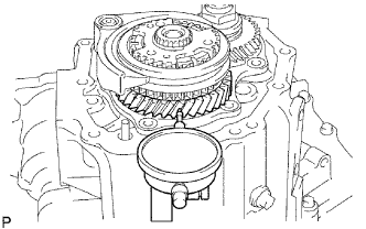
INSTALL DIFFERENTIAL CASE ASSEMBLY
INSTALL OUTPUT SHAFT ASSEMBLY
INSTALL INPUT SHAFT ASSEMBLY
INSTALL NO. 2 GEAR SHIFT FORK
INSTALL NO. 3 GEAR SHIFT FORK
INSTALL NO. 1 GEAR SHIFT FORK
INSTALL NO. 2 GEAR SHIFT FORK
INSTALL REVERSE SHIFT FORK ROLLER
INSTALL NO. 1 GEAR SHIFT FORK SHAFT
INSTALL REVERSE SHIFT ARM BRACKET ASSEMBLY
INSTALL REVERSE IDLER GEAR SUB-ASSEMBLY
INSTALL TRANSAXLE MAGNET
INSTALL REVERSE RESTRICT PIN ASSEMBLY
INSTALL NO. 1 OIL RECEIVER PIPE
INSTALL NO. 2 OIL RECEIVER PIPE
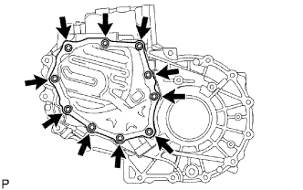
INSTALL MANUAL TRANSAXLE CASE
INSTALL CLUTCH TUBE BRACKET
INSTALL REVERSE IDLER GEAR SHAFT BOLT
INSTALL SHIFT FORK SHAFT SHAFT SNAP RING
INSTALL INPUT SHAFT REAR BEARING SHAFT SNAP RING
INSTALL OUTPUT SHAFT REAR BEARING SHIM
INSTALL REAR BEARING RETAINER
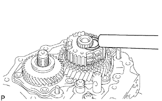
INSTALL 5TH DRIVEN GEAR
INSTALL 5TH GEAR NEEDLE ROLLER BEARING
INSTALL 5TH GEAR
INSTALL NO. 3 TRANSAXLE CLUTCH HUB
INSPECT 5TH GEAR RADIAL CLEARANCE
INSPECT 5TH GEAR THRUST CLEARANCE
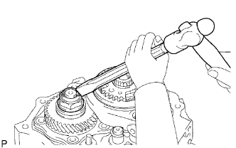
INSTALL TRANSAXLE OUTPUT SHAFT REAR SET NUT
INSTALL MANUAL TRANSAXLE CASE COVER SUB-ASSEMBLY
INSTALL DRAIN PLUG SUB-ASSEMBLY
INSTALL MANUAL TRANSAXLE FILLER PLUG
INSTALL SHIFT AND SELECT LEVER SHAFT ASSEMBLY
INSTALL CONTROL SHAFT COVER
INSTALL BACK-UP LIGHT SWITCH ASSEMBLY
INSTALL MANUAL TRANSAXLE BREATHER PLUG
INSTALL NO. 1 LOCK BALL ASSEMBLY
INSTALL CONTROL SHIFT LEVER
INSTALL SELECTING BELLCRANK ASSEMBLY
INSTALL SPEEDOMETER DRIVEN HOLE COVER SUB-ASSEMBLY
INSTALL CLUTCH RELEASE FORK BOOT
INSTALL RELEASE FORK SUPPORT
INSTALL CLUTCH RELEASE BEARING ASSEMBLY
INSTALL CLUTCH RELEASE FORK SUB-ASSEMBLY
Manual Transaxle Unit -- Reassembly |
| 1. INSTALL SYNCHRONIZER PULL RING |
Install the No. 5 synchronizer ring middle, No. 5 synchronizer ring outer and synchronizer pull ring to the No. 5 synchronizer ring inner. Using a screwdriver, fix them in place with the synchronizer pull ring snap ring.
| 2. INSTALL NO. 5 SYNCHRONIZER RING MIDDLE |
Check that the No. 5 synchronizer ring middle rotates smoothly.
Check that the No. 5 synchronizer ring middle does not rotate while being pushed against the No. 3 clutch hub.
| 3. INSTALL NO. 3 SYNCHROMESH SHIFTING KEY SPRING |
Install the No. 3 synchromesh shifting key spring to the No. 3 transaxle clutch hub.
- NOTICE:
- Align the projection of the shifting key spring with the hole of the No. 3 clutch hub and install it.
Install the synchronizer ring set and No. 3 synchromesh shifting key spring to the No. 3 transaxle clutch hub.
- NOTICE:
- Engage the shifting key spring claw to the center of the teeth of the synchronizer ring.
- Align the projection of the shifting key spring with the hole of the No. 3 clutch hub and install it.
| 4. INSTALL FRONT TRANSAXLE CASE COVER OIL SEAL |
Using SST and a hammer, tap in a new front transaxle case cover oil seal.
- SST
- 09316-20011
09950-60020(09951-00910)
09950-70010(09951-07150)
- Standard depth:
- -0.5 to 0.5 mm (-0.020 to 0.020 in.)
Coat the lip of the oil seal with MP grease.
| 5. INSTALL FRONT DIFFERENTIAL CASE FRONT TAPERED ROLLER BEARING |
Using SST and a hammer, tap in the front tapered roller bearing (outer race) to the front differential case.
- SST
- 09950-60020(09951-00910)
09950-70010(09951-07100,09951-07150)
Using SST and a press, press in the front tapered roller bearing (inner race) to the front differential case.
- SST
- 09950-70010(09951-07100,09951-07150)
09608-10010
| 6. INSTALL FRONT DIFFERENTIAL CASE REAR TAPERED ROLLER BEARING |
Install the rear shim.
Using SST and a hammer, tap in the rear tapered roller bearing (outer race).
- SST
- 09950-60020(09951-00890)
09950-70010(09951-07100)
Using SST and a press, press in the rear tapered roller bearing (inner race).
- SST
- 09631-12090
09950-60010(09951-00600)
09950-70010(09951-07100)
| 7. INSTALL TRANSAXLE CASE OIL SEAL |
Using SST and a hammer, tap in a new oil seal to the transaxle case.
- SST
- 09608-32010
09950-70010(09951-07150)
- Standard depth:
- 3.0 to 4.0 mm (0.118 to 0.158 in.)
Coat the oil seal lip with MP grease.
| 8. INSTALL REAR OUTPUT SHAFT BEARING |
Using SST and a hammer, tap in the rear bearing (outer race) to the transaxle case.
- SST
- 09950-60020(09951-00680)
09950-70010(09951-07100)
- Standard clearance:
- 3.8 to 4.4 mm (0.150 to 0.173 in.)
| 9. INSTALL OUTPUT SHAFT COVER |
Coat the shaft cover with MP grease, and install it to the transaxle case.
- NOTICE:
- Align the projection of the output shaft with the transaxle groove and install it.
| 10. INSTALL FRONT OUTPUT SHAFT BEARING |
Using SST and a hammer, tap in the front bearing (outer race).
- SST
- 09950-60020(09951-00730)
09950-70010(09951-07100)
| 11. ADJUST OUTPUT SHAFT BEARING PRELOAD |
Install the output shaft to the transaxle case.
Install the transaxle case to the transaxle case with the 14 bolts.
- Torque:
- 29 N*m{296 kgf*cm, 21 ft.*lbf}
Install the 3 bolts on the transaxle side.
- Torque:
- 29 N*m{296 kgf*cm, 21 ft.*lbf}
Install the output shaft rear bearing shim to the output shaft.
Using a T45 "torx" socket, install the rear bearing retainer to the transaxle case with the 7 "torx" screws.
- Torque:
- 43 N*m{438 kgf*cm, 32 ft.*lbf}
Turn the output shaft in both directions and check that it turns smoothly.
Temporarily install the output shaft rear set nut.
Using a socket wrench and torque wrench, inspect the preload.
- Standard preload:
Bearing
| Specified Condition
|
New
| 0.8 to 1.6 N*m (8.16 to 16.32 kgf*cm, 7.1 to 14.2 in.lbf)
|
Used
| 0.5 to 1.0 N*m (5.10 to 10.20 kgf*cm, 4.4 to 8.9 in.lbf)
|
If preload is out of the specification, select a proper output shaft rear bearing shim and adjust the preload.
- HINT:
- The preload of all the output shaft rear bearing shims varies in torque from about 0.04 to 0.06 N*m (0.408 to 0.612 kgf*cm, 0.354 to 0.531 in.*lbf).
- Standard shim thickness:
Part No
| Mark
| Thickness
|
90564-59001
| 0
| 1.30 mm (0.0512 in.)
|
90564-59002
| 1
| 1.35 mm (0.0531 in.)
|
90564-59003
| 2
| 1.40 mm (0.0551 in.)
|
90564-59004
| 3
| 1.45 mm (0.0571 in.)
|
90564-59005
| 4
| 1.50 mm (0.0591 in.)
|
90564-59006
| 5
| 1.55 mm (0.0610 in.)
|
90564-59007
| 6
| 1.60 mm (0.0630 in.)
|
90564-59008
| 7
| 1.65 mm (0.0650 in.)
|
90564-59009
| 8
| 1.70 mm (0.0669 in.)
|
90564-59010
| 9
| 1.75 mm (0.0689 in.)
|
90564-59011
| A
| 1.80 mm (0.0669 in.)
|
90564-59012
| B
| 1.85 mm (0.0728 in.)
|
90564-59013
| C
| 1.90 mm (0.0748 in.)
|
90564-59014
| D
| 1.95 mm (0.0768 in.)
|
90564-59015
| E
| 2.00 mm (0.787 in.)
|
90564-59016
| F
| 2.05 mm (0.0807 in.)
|
90564-59017
| G
| 2.10 mm (0.0827 in.)
|
90564-59018
| H
| 2.15 mm (0.0846 in.)
|
90564-59019
| J
| 2.20 mm (0.0866 in. )
|
90564-59020
| K
| 2.25 mm (0.0886 in.)
|
90564-59021
| L
| 2.30 mm (0.0906 in.)
|
90564-59022
| M
| 2.35 mm (0.0925 in.)
|
90564-59023
| N
| 2.40 mm (0.0945 in.)
|
90564-59024
| P
| 2.45 mm (0.0965 in.)
|
90564-59025
| Q
| 2.50 mm (0.0984 in.)
|
Remove the output shaft rear set nut from the output shaft.
Using a T45 "torx" socket, remove the 7 "torx" screws and rear bearing retainer from the manual transaxle case.
Remove the output shaft rear bearing shim from the output shaft.
Remove the 3 bolts.
Remove the 14 bolts and transaxle case from the transaxle case.
Remove the output shaft assembly from the front transaxle case.
| 12. ADJUST TAPERED ROLLER BEARING PRELOAD |
Install the bearing to the transaxle case.
Install the 14 bolts and transaxle case to the transaxle case.
- Torque:
- 29 N*m{296 kgf*cm, 21 ft.*lbf}
Install the 3 bolts on the front transaxle case side.
- Torque:
- 29 N*m{296 kgf*cm, 21 ft.*lbf}
Turn the differential case in both directions and check that it turns smoothly.
|
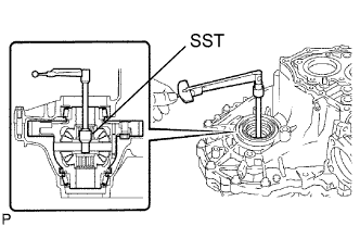
Using SST and a torque wrench, measure the preload.
- SST
- 09564-32011
- Standard preload:
Bearing
| Specified Condition
|
New
| 0.8 to 1.6 N*m (8.16 to 16.32 kgf*cm, 7.1 to 14.2 in.*lbf)
|
Used
| 0.5 to 1.0 N*m (5.10 to 10.2 kgf*cm, 4.4 to 8.9 in.*lbf)
|
If the preload is out of the specification, select a proper front differential case rear shim and adjust the preload.
- HINT:
- The preload of all the front differential case rear shims varies in torque from about 0.04 to 0.06 N*m (0.408 to 0.612 kgf*cm, 0.354 to 0.531 in.*lbf).
- Standard shim thickness:
Part No.
| Mark
| Thickness
|
90564-56055
| 0
| 2.00 mm (0.0787 in.)
|
90564-56056
| 1
| 2.05 mm (0.0807 in.)
|
90564-56057
| 2
| 2.10 mm (0.0827 in.)
|
90564-56058
| 3
| 2.15 mm (0.0846 in.)
|
90564-56059
| 4
| 2.20 mm (0.0866 in.)
|
90564-56060
| 5
| 2.25 mm (0.0886 in.)
|
90564-56061
| 6
| 2.30 mm (0.0906 in.)
|
90564-56062
| 7
| 2.35 mm (0.0925 in.)
|
90564-56063
| 8
| 2.40 mm (0.0945 in.)
|
90564-56064
| 9
| 2.45 mm (0.0965 in.)
|
90564-56065
| A
| 2.50 mm (0.0984 in.)
|
90564-56066
| B
| 2.55 mm (0.1004 in.)
|
90564-56067
| C
| 2.60 mm (0.1024 in.)
|
90564-56068
| D
| 2.65 mm (0.1043 in.)
|
90564-56069
| E
| 2.70 mm (0.1063 in.)
|
90564-56070
| F
| 2.75 mm (0.1083 in.)
|
90564-56071
| G
| 2.80 mm (0.1102 in.)
|
90564-56072
| H
| 2.85 mm (0.1122 in.)
|
Remove the 3 bolts.
Remove the 14 bolts and transaxle case from the transaxle case.
Remove the bearing from the transaxle case.
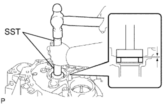
| 13. INSTALL FRONT TRANSAXLE CASE OIL SEAL |
Using SST and a hammer, tap in a new oil seal to the transaxle case.
- SST
- 09950-60010(09951-00420)
09950-70010(09951-07150)
- Standard distance:
- 1 to 2 mm (0.04 to 0.08 in.)
Coat the lip of the oil seal with MP grease.
| 14. INSTALL FRONT INPUT SHAFT BEARING |
Coat the input shaft front bearing with gear oil, and using SST, tap in it to the transaxle case.
- SST
- 09950-60010(09951-00570)
09950-70010(09951-07150)
- Standard distance:
- 4.28 to 4.60 mm (0.1685 to 0.1811 in.)
| 15. INSTALL MANUAL TRANSAXLE CASE RECEIVER |
Install the receiver to the transaxle case with the 3 bolts.
- Torque:
- 7.0 N*m{71 kgf*cm, 62 in.*lbf}
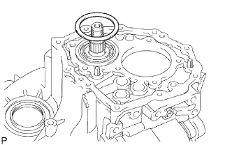
| 16. INSTALL DIFFERENTIAL CASE ASSEMBLY |
Coat the differential case tapered roller bearing with gear oil, and install the differential case to the transaxle case.
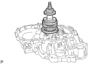
| 17. INSTALL OUTPUT SHAFT ASSEMBLY |
Apply gear oil to each sliding part of the output shaft.
Slightly lift up on the differential case at an angle, and install the output shaft to the transaxle case.
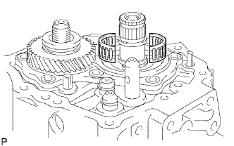
| 18. INSTALL INPUT SHAFT ASSEMBLY |
Apply gear oil to each sliding part of the input shaft.
Install the input shaft to the transaxle case while tilting the output shaft.
| 19. INSTALL NO. 2 GEAR SHIFT FORK |
Coat the No. 2 gear shift fork with gear oil, and install it to the input shaft assembly.
| 20. INSTALL NO. 3 GEAR SHIFT FORK |
Install the reverse shift fork to the No. 3 gear shift fork shaft.
Using a brass bar and hammer, tap in the 2 shift fork shaft snap rings to the No. 3 gear shift fork shaft.
Apply gear oil to each sliding part of the No. 3 gear shift fork shaft, and install it to the transaxle case.
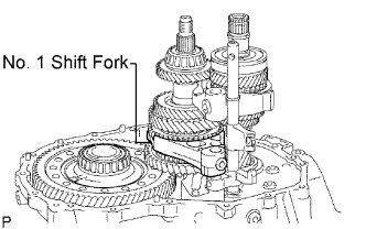
| 21. INSTALL NO. 1 GEAR SHIFT FORK |
Apply gear oil to each sliding part of the No. 1 gear shift fork, and install it to the output shaft assembly.
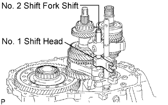
| 22. INSTALL NO. 2 GEAR SHIFT FORK |
Apply gear oil to each sliding part of the No. 2 gear shift fork shaft and No. 1 gear shift head, and install them to the transaxle case.
Install the shift fork set bolt and shift head set bolt to the No. 1 gear shift head and No. 2 gear shift fork.
- Torque:
- 24 N*m{245 kgf*cm, 18 ft.*lbf}
| 23. INSTALL REVERSE SHIFT FORK ROLLER |
Using a magnetic finger, install the reverse shift fork roller to the reverse shift fork.
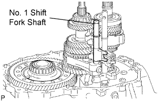
| 24. INSTALL NO. 1 GEAR SHIFT FORK SHAFT |
Using a brass bar and hammer, tap in the shaft snap ring to the No. 1 shift fork shaft.
Install the No. 1 gear shift fork shaft to the transaxle case.
Install the shift fork set bolt to the No. 1 gear shift fork.
- Torque:
- 24 N*m{245 kgf*cm, 18 ft.*lbf}
| 25. INSTALL REVERSE SHIFT ARM BRACKET ASSEMBLY |
Install the reverse shift arm bracket to the transaxle case with the 2 bolts.
- Torque:
- 17 N*m{173 kgf*cm, 13 ft.*lbf}
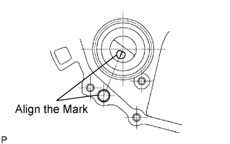
| 26. INSTALL REVERSE IDLER GEAR SUB-ASSEMBLY |
Coat the reverse idler gear and thrust washer with gear oil, and install them to the reverse idler gear shaft.
Install the reverse idler gear with the reverse idler gear shaft to the transaxle case.
- HINT:
- Align the mark of the reverse idler gear shaft with the hole of the bolts.
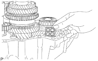
| 27. INSTALL TRANSAXLE MAGNET |
Clean the transaxle magnet, and install it to the transaxle case.
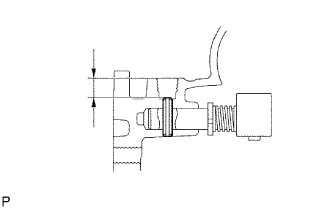
| 28. INSTALL REVERSE RESTRICT PIN ASSEMBLY |
Install the transmission oil baffle and reverse restrict pin with the bolt.
- Torque:
- 17 N*m{173 kgf*cm, 13 ft.*lbf}
Install the reverse restrict pin to the transaxle case.
Using a 5 mm pin punch and hammer, tap in the slotted spring pin.
- Standard clearance:
- 12.5 to 13.5 mm (0.492 to 0.531 in.)
Coat the reverse restrict pin plug with adhesive. Using a 6 mm hexagon wrench, install the plug to the manual transaxle case.
- Adhesive:
- Toyota Genuine Adhesive 1324, Three Bond 1324 or Equivalent
- Torque:
- 13 N*m{133 kgf*cm, 9.6 ft.*lbf}
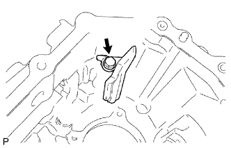
| 29. INSTALL NO. 1 OIL RECEIVER PIPE |
Install the oil receiver pipe to the transaxle case with the bolt.
- Torque:
- 17 N*m{173 kgf*cm, 13 ft.*lbf}
- NOTICE:
- Do not damage the pipe.
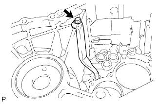
| 30. INSTALL NO. 2 OIL RECEIVER PIPE |
Install the oil receiver pipe to the transaxle case with the bolt.
- Torque:
- 17 N*m{173 kgf*cm, 13 ft.*lbf}
- NOTICE:
- Do not damage the pipe.
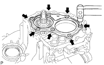
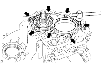
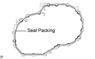
| 31. INSTALL MANUAL TRANSAXLE CASE |
Apply seal packing to the transaxle case in a continuous line, as shown in the illustration.
- Seal packing:
- Toyota Genuine Seal Packing Black, Three Bond 1207B or Equivalent
- NOTICE:
- Install the part within 10 minutes after applying packing material.
Install the transaxle case to the transaxle case with the 14 bolts.
- Torque:
- 29 N*m{296 kgf*cm, 21 ft.*lbf}
Coat the 3 bolts with adhesive, and install them on the transaxle case side.
- Torque:
- 29 N*m{296 kgf*cm, 21 ft.*lbf}
- Adhesive:
- Toyota Genuine Adhesive 1344, Three Bond 1344 or Equivalent
| 32. INSTALL CLUTCH TUBE BRACKET |
Install the clutch tube bracket with the bolt.
- Torque:
- 17 N*m{173 kgf*cm, 13 ft.*lbf}
| 33. INSTALL REVERSE IDLER GEAR SHAFT BOLT |
Coat the reverse idler gear shaft bolt with adhesive, and install a new reverse idler gear shaft gasket and the reverse idler gear shaft bolt to the transaxle case.
- Torque:
- 30 N*m{306 kgf*cm, 22 ft.*lbf}
- Adhesive:
- Toyota Genuine Adhesive 1344, Three Bond 1344 or equivalent
| 34. INSTALL SHIFT FORK SHAFT SHAFT SNAP RING |
Using a brass bar and hammer, tap in the shaft snap ring to the No. 1 gear shift fork shaft.
Using a brass bar and hammer, tap in the shaft snap ring to the No. 2 gear shift fork shaft.
| 35. INSTALL INPUT SHAFT REAR BEARING SHAFT SNAP RING |
Using a snap ring expander, install the shaft snap ring.
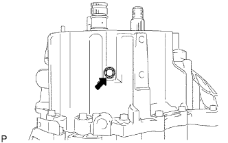
| 36. INSTALL OUTPUT SHAFT REAR BEARING SHIM |
Install the output shaft rear bearing shim to the output shaft.
| 37. INSTALL REAR BEARING RETAINER |
Coat the 7 bolts with adhesive. Using a T45 "torx" socket, install the bearing retainer with the bolts.
- Torque:
- 43 N*m{438 kgf*cm, 32 ft.*lbf}
- Adhesive:
- Toyota Genuine Adhesive 1344, Three Bond 1344 or Equivalent
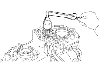
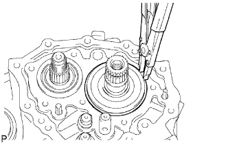
| 38. INSTALL 5TH DRIVEN GEAR |
Using SST, install the 5th driven gear to the output shaft.
- SST
- 09309-12020
| 39. INSTALL 5TH GEAR NEEDLE ROLLER BEARING |
Coat the needle roller bearing with gear oil, and install it to the input shaft.
Coat the 5th gear with gear oil, and install it to the input shaft.
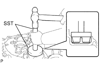
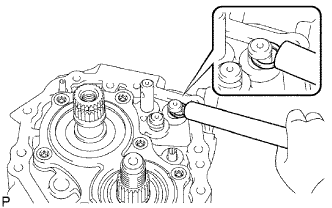
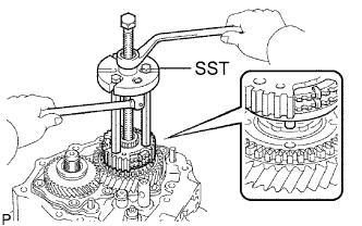
| 41. INSTALL NO. 3 TRANSAXLE CLUTCH HUB |
Using SST, install the No. 3 transaxle clutch hub to the input shaft.
- SST
- 09950-30012(09951-03010,09953-03010,09954-03010)
- NOTICE:
- Align the projection of the synchronizer ring with the hole of the 5th gear and install it.
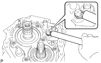
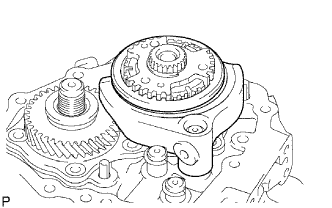
Install the No. 3 transaxle hub sleeve and No. 3 gear shift fork to the No. 3 transaxle clutch hub.
Coat the shift fork set bolt with adhesive, and install it to the No. 3 gear shift fork.
- Torque:
- 24 N*m{245 kgf*cm, 18 ft.*lbf}
- Adhesive:
- Toyota Genuine Adhesive 1344, Three Bond 1344 or Equivalent
Select an appropriate No. 3 transaxle clutch hub shaft snap ring that allows the minimum amount of axial play. Using a brass bar and hammer, tap in the No. 3 transaxle clutch hub shaft snap ring.
- Standard clearance:
- 0.1 mm (0.004 in.) or less
- Standard snap ring:
Part No.
| Mark
| Thickness
|
90520-27061
| a
| 1.75 to 1.80 mm (0.0689 to 0.0709 in.)
|
90520-27062
| b
| 1.80 to 1.85 mm (0.0709 to 0.0728 in.)
|
90520-27063
| c
| 1.85 to 1.90 mm (0.0728 to 0.0748 in.)
|
90520-27064
| d
| 1.90 to 1.95 mm (0.0748 to 0.0768 in.)
|
90520-27065
| e
| 1.95 to 2.00 mm (0.0768 to 0.0787 in.)
|
90520-27066
| f
| 2.00 to 2.05 mm (0.0787 to 0.0807 in.)
|
90520-27067
| g
| 2.05 to 2.10 mm (0.0807 to 0.0827 in.)
|
90520-27068
| h
| 2.10 to 2.15 mm (0.0827 to 0.0846 in.)
|
90520-27069
| j
| 2.15 to 2.20 mm (0.0846 to 0.0866 in.)
|
| 42. INSPECT 5TH GEAR RADIAL CLEARANCE |
Using a dial indicator, measure the 5th gear radial clearance.
- Standard clearance:
- 0.009 to 0.050 mm (0.0004 to 0.0020 in.)
If the clearance is out of the specification, replace the 5th gear, 5th gear needle roller bearing or input shaft.
| 43. INSPECT 5TH GEAR THRUST CLEARANCE |
Using a dial indicator, measure the 5th gear thrust clearance.
- Standard clearance:
- 0.10 to 0.65 mm (0.0039 to 0.0260 in.)
If the clearance is out of the specification, replace the No. 3 transaxle clutch hub, 5th gear or input shaft rear radial ball bearing.
| 44. INSTALL TRANSAXLE OUTPUT SHAFT REAR SET NUT |
Engage the 2 gears simultaneously to lock the transaxle.
Install a new transaxle output shaft rear set nut.
- Torque:
- 123 N*m{1,254 kgf*cm, 90 ft.*lbf}
Using a chisel and hammer, stake the rear set nut.
Disengage the 2 gears.
| 45. INSTALL MANUAL TRANSAXLE CASE COVER SUB-ASSEMBLY |
Apply seal packing to the transaxle case cover, as shown in the illustration.
- Seal packing:
- Toyota Genuine Seal Packing Black, Three Bond 1207B or Equivalent
- NOTICE:
- Install the part within 10 minutes after applying packing material.
Install the transaxle case cover to the transaxle case with the 10 bolts.
- Torque:
- 29 N*m{296 kgf*cm, 21 ft.*lbf}
| 46. INSTALL DRAIN PLUG SUB-ASSEMBLY |
Install a new gasket and the drain plug to the transaxle case.
- Torque:
- 49 N*m{500 kgf*cm, 36 ft.*lbf}
| 47. INSTALL MANUAL TRANSAXLE FILLER PLUG |
Install a new gasket and the filler plug to the transaxle case.
- Torque:
- 49 N*m{500 kgf*cm, 36 ft.*lbf}
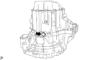
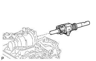
| 48. INSTALL SHIFT AND SELECT LEVER SHAFT ASSEMBLY |
Coat the shift and select lever shaft with gear oil, and install it to the transaxle case.
| 49. INSTALL CONTROL SHAFT COVER |
Coat the 4 bolts with adhesive, and install a new gasket and the control shaft cover with the 4 bolts.
- Adhesive:
- Toyota Genuine Adhesive 1344, Three Bond 1344 or Equivalent
- Torque:
- 20 N*m{204 kgf*cm, 15 ft.*lbf}
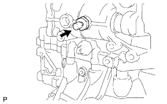
| 50. INSTALL BACK-UP LIGHT SWITCH ASSEMBLY |
Install a new gasket and the back-up light switch to the manual transaxle case.
- Torque:
- 40 N*m{408 kgf*cm, 30 ft.*lbf}
| 51. INSTALL MANUAL TRANSAXLE BREATHER PLUG |
Install a new gasket and the breather plug to the case.
- Torque:
- 49 N*m{500 kgf*cm, 36 ft.*lbf}
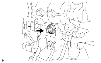
| 52. INSTALL NO. 1 LOCK BALL ASSEMBLY |
Install the No. 1 lock ball to the transaxle case.
- Torque:
- 29 N*m{296 kgf*cm, 21 ft.*lbf}
| 53. INSTALL CONTROL SHIFT LEVER |
Install the control shift lever with the shift outer lever lock pin to the shift and select lever shaft.
Install the spring washer with the nut.
- Torque:
- 6.4 N*m{65 kgf*cm, 57 in.*lbf}
| 54. INSTALL SELECTING BELLCRANK ASSEMBLY |
Install the shift and select lever bush to the selecting bellcrank.
Coat the 2 bolts with adhesive, and install the selecting bellcrank to the transaxle case with the bolts.
- Adhesive:
- Toyota Genuine Adhesive 1344, Three Bond 1344 or Equivalent
- Torque:
- 20 N*m{204 kgf*cm, 15 ft.*lbf}
| 55. INSTALL SPEEDOMETER DRIVEN HOLE COVER SUB-ASSEMBLY |
Install a new O-ring to the hole cover.
Install the hole cover to the transaxle case with the bolt.
- Torque:
- 5.5 N*m{56 kgf*cm, 48 ft.*lbf}
| 56. INSTALL CLUTCH RELEASE FORK BOOT |
Install the clutch release fork boot to the transaxle case.
| 57. INSTALL RELEASE FORK SUPPORT |
Using a deep socket wrench, install the release fork support to the transaxle case.
- Torque:
- 47 N*m{480 kgf*cm, 35 in.*lbf}
| 58. INSTALL CLUTCH RELEASE BEARING ASSEMBLY |
Coat the clutch release bearing with Multemp 8158 Grease or equivalent, and install it to the clutch release fork with the clutch release bearing clip.
- Grease:
- Multemp 8158 Grease or equivalent
| 59. INSTALL CLUTCH RELEASE FORK SUB-ASSEMBLY |
Apply clutch spline grease to the input shaft spline.
Install the clutch release fork to the input shaft.
- Grease:
- Toyota Genuine Clutch Spline Grease or equivalent