Clutch Master Cylinder (For Lhd) -- Installation |
| 1. INSTALL CLUTCH MASTER CYLINDER ASSEMBLY |
Install the clutch master cylinder with the 2 nuts.
- Torque:
- 13 N*m{130 kgf*cm, 9 ft.*lbf}
| 2. CONNECT CLUTCH MASTER CYLINDER TO FLEXIBLE HOSE TUBE |
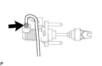 |
Using a union nut wrench, connect the flexible hose tube.
- Torque:
- 15 N*m{153 kgf*cm, 11 ft.*lbf}
- NOTICE:
- Use the formula to calculate special torque values for situations where a union nut wrench is combined with a torque wrench (RAV4_ACA30 RM0000018UO018X.html).
| 3. CONNECT CLUTCH RESERVOIR TUBE |
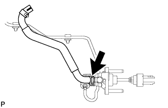 |
Connect the clutch reservoir tube to the clutch master cylinder with the clip.
- NOTICE:
- Connect the clutch reservoir tube so that it will not be twisted.
- Face the yellow mark upward.
| 4. CONNECT CLUTCH MASTER CYLINDER PUSH ROD CLEVIS |
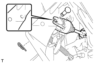 |
Apply MP grease to the contact surface of the pin and clevis bush.
Connect the clevis to the clutch pedal with the pin and clip.
- HINT:
- Install the pin from the right side of the vehicle.
Install the clip to the pin.
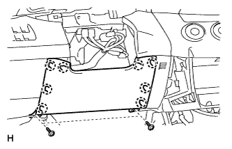
| 5. INSTALL DRIVER SIDE KNEE AIRBAG ASSEMBLY (w/ Knee Airbag) |
 |
Connect the connector.
- NOTICE:
- When handling the airbag connector, take care not to damage the airbag wire harness.
Install the driver side knee airbag with the 4 bolts.
- Torque:
- 10 N*m{101 kgf*cm, 7 ft.*lbf}
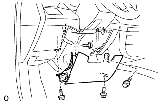
| 6. INSTALL LOWER INSTRUMENT PANEL FINISH PANEL (w/o Knee Airbag) |
 |
Attach the 8 claws to install the lower instrument panel finish panel.
Install the 2 screws.
| 7. INSTALL NO. 1 INSTRUMENT PANEL UNDER COVER SUB-ASSEMBLY |
Attach the 3 claws to install the cover.
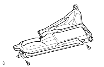 |
Install the 2 screws.
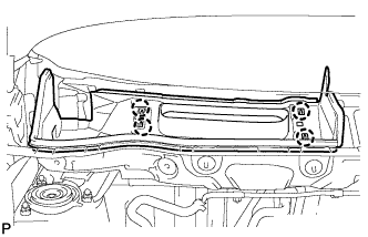
| 8. INSTALL COWL BODY MOUNTING REINFORCEMENT LH |
 |
Install the mounting reinforcement with the 2 nuts.
| 9. INSTALL COWL TOP PANEL OUTER SUB-ASSEMBLY |
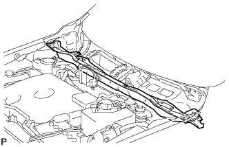 |
Install the cowl top panel outer with the 14 bolts.
- Torque:
- 6.5 N*m{66 kgf*cm, 58 in.*lbf}
| 10. INSTALL COWL VENTILATOR HOUSING SUB-ASSEMBLY |
 |
Attach the 4 claws to install ventilator housing.
| 11. INSTALL WINDSHIELD WIPER MOTOR AND LINK ASSEMBLY |
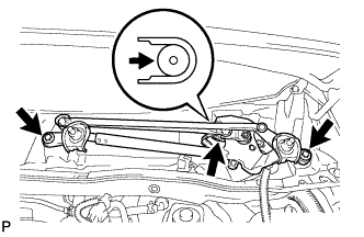 |
Connect the connector and attach the clamp.
Move the wiper motor and link in the direction shown by the arrow in the illustration to attach the wiper cushion to the body, and install the wiper motor and link.
Install the 2 bolts.
- Torque:
- 5.5 N*m{56 kgf*cm, 49 in.*lbf}
| 12. INSTALL COWL TOP VENTILATOR LOUVER |
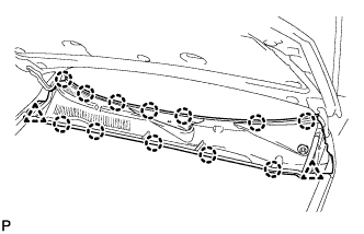 |
Attach the 12 claws and install the louver.
Install the 2 clips.
| 13. INSTALL FRONT FENDER TO COWL SIDE SEAL LH |
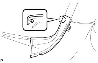 |
Attach the claw to install the front fender to cowl side seal.
| 14. INSTALL FRONT FENDER TO COWL SIDE SEAL RH |
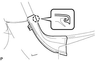 |
Attach the claw to install the front fender to cowl side seal.
| 15. INSTALL FRONT WIPER ARM AND BLADE ASSEMBLY LH |
Clean the wiper arm serration with a round file or equivalent.
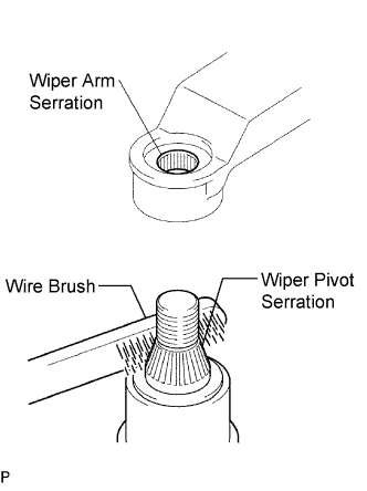 |
Clean the wiper pivot serration with a wire brush.
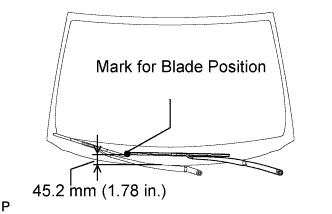
Install the arm and blade with the nut. Make sure that the arm and blade comes to the position shown in the illustration.
- Torque:
- 26 N*m{265 kgf*cm, 19 ft.*lbf}
- HINT:
- Hold down the arm hinge with your hand while tightening the nut.
 |
Operate the front wipers while spraying water or washer fluid on the windshield. Ensure that there is no interference between the blades and pillar.
| 16. INSTALL FRONT WIPER ARM AND BLADE ASSEMBLY RH |
Stop the wiper motor at the automatic stop position.
|
Clean the wiper arm serration with a round file or equivalent.
Clean the wiper pivot serration with a wire brush.
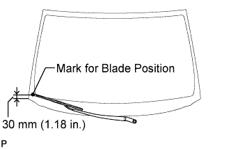
Install the arm and blade with the nut. Make sure that the arm and blade comes to the position shown in the illustration.
- Torque:
- 26 N*m{265 kgf*cm, 19 ft.*lbf}
- HINT:
- Hold down the arm hinge with your hand while tightening the nut.
 |
| 17. INSTALL FRONT WIPER ARM HEAD CAP |
Install the 2 caps.
| 18. CONNECT CABLE TO NEGATIVE BATTERY TERMINAL |
| 19. CHECK SRS WARNING LIGHT |
Check the SRS warning light (RAV4_ACA30 RM000000XFD06JX.html).
| 20. BLEED CLUTCH PIPE LINE |
Fill the brake reservoir with brake fluid and bleed the clutch system.
- Torque:
- 8.3 N*m{85 kgf*cm, 73 in.*lbf}
| 21. CHECK BRAKE FLUID |
Check the brake fluid (RAV4_ACA30 RM000001HJ200GX.html).
- HINT:
- Check for leakage in the brake system.
- Check for leakage in the clutch system.
| 22. CHECK FLUID LEVEL IN RESERVOIR |
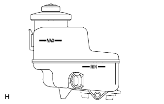 |
Check the fluid level and add fluid if necessary.
- Fluid:
- SAE J1703 or FMVSS No. 116 DOT3
- HINT:
- Add fluid to a level between the reservoir's MIN and MAX lines.
| 23. INSPECT AND ADJUST CLUTCH PEDAL SUB-ASSEMBLY |
Lift up the floor carpet to expose the asphalt sheet under the pedal.
Check that the pedal height is correct.
- Standard pedal height from floor:
- for 1AZ-FE, 3ZR-FAE:
- 162.9 to 172.9 mm (6.41 to 6.81 in.)
- for 2AZ-FE, 2AD-FTV, 2AD-FHV:
- 175.7 to 185.7 mm (6.92 to 7.31 in.)
 |
Adjust the pedal height.
Loosen the lock nut and turn the stopper bolt or clutch switch assembly until the pedal height is within the specified range.
Tighten the lock nut.
- Torque:
- 16 N*m{163 kgf*cm, 12 ft.*lbf}
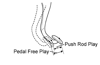
Check the pedal free play and push rod play.
Depress the clutch pedal until resistance is felt.
Measure the distance between the pedal's released position and the position in the previous step.
- Standard pedal free play:
- 5.0 to 15.0 mm (0.197 to 0.591 in.)
Release the pedal. Using your finger, gently press the pedal until resistance increases slightly.
Measure the distance between the pedal's released position and the position in the previous step.
- Standard push rod play at pedal top:
- 1.0 to 5.0 mm (0.0394 to 0.197 in.)
 |
Adjust the pedal free play and push rod play.
Loosen the lock nut and turn the push rod until the pedal free play and push rod play are within the specified ranges.
- NOTICE:
- When loosening the lock nut, be sure to hold the clevis in place by its hexagonal portion.
Tighten the lock nut.
- Torque:
- 12 N*m{120 kgf*cm, 9 ft.*lbf}
- NOTICE:
- When tightening the lock nut, be sure to hold the clevis in place by its hexagonal portion.
Check the pedal height.
Check the clutch release point.
Apply the parking brake and use wheel chocks.
Start the engine and run it at idle.
Without depressing the clutch pedal, slowly move the shift lever to R until the gears contact.
Gently depress the clutch pedal and measure the stroke distance from the point that the gear noise stops (release point) to the full stroke end position.
- Standard distance:
- 25 mm (0.984 in.) or more
- Check pedal height.
- Check push rod play and pedal free play.
- Bleed air from clutch line.
- Check clutch cover and disc.
 |