Automatic Transaxle Unit Inspection
INSPECT MULTIPLE DISC CLUTCH HUB
INSPECT NO. 2 UNDERDRIVE CLUTCH DISC
INSPECT OVERDRIVE DIRECT CLUTCH DRUM SUB-ASSEMBLY
INSPECT 2ND BRAKE CLUTCH DISC
INSPECT 1ST AND REVERSE BRAKE CLUTCH DISC
INSPECT 1ST AND REVERSE BRAKE RETURN SPRING SUB-ASSEMBLY
INSPECT UNDERDRIVE BRAKE RETURN SPRING SUB-ASSEMBLY
INSPECT PACK CLEARANCE OF 1ST AND REVERSE BRAKE
INSPECT PACK CLEARANCE OF 2ND BRAKE
INSPECT PACK CLEARANCE OF UNDERDRIVE BRAKE
INSPECT UNDERDRIVE ONE-WAY CLUTCH ASSEMBLY
INSPECT INPUT SHAFT END PLAY
Automatic Transaxle Unit -- Inspection |
| 1. INSPECT MULTIPLE DISC CLUTCH HUB |
Using a caliper gauge, measure the inside diameter of the forward clutch hub bushing.
- Standard inside diameter:
- 23.03 to 23.05 mm (0.9067 to 0.9075 in.)
- Maximum inside diameter:
- 23.09 mm (0.9091 in.)
- NOTICE:
- Check the contact surface of the bushing in the direct clutch shaft. If any scratches or discoloration is found, replace the direct clutch assembly with a new one.
If the inside diameter is greater than the maximum, replace the forward clutch hub with a new one.
| 2. INSPECT NO. 2 UNDERDRIVE CLUTCH DISC |
Check if the sliding surfaces of the discs, plates and flange are worn or burnt.
If necessary, replace them.
- NOTICE:
- If the lining of a disc comes off or is discolored, or if a part of the groove is worn, replace all the discs.
- Before installing new discs, immerse them in ATF for at least 15 minutes.
| 3. INSPECT OVERDRIVE DIRECT CLUTCH DRUM SUB-ASSEMBLY |
Using a caliper gauge, measure the inside diameter of the forward clutch hub bushing.
- Standard inside diameter:
- 23.025 to 23.046 mm (0.9065 to 0.9073 in.)
- Maximum inside diameter:
- 23.09 mm (0.9091 in.)
- NOTICE:
- Check the contact surface of the bushing in the direct clutch shaft. If any scratches or discoloration is found, replace the direct clutch assembly with a new one.
If the inside diameter is greater than the maximum, replace the forward clutch hub with a new one.
| 4. INSPECT 2ND BRAKE CLUTCH DISC |
Check if the sliding surfaces of the discs, plates and flange are worn or burnt.
If necessary, replace them.
- NOTICE:
- If the lining of a disc comes off or is discolored, or if a part of the groove is worn, replace all the discs.
- Before installing new discs, immerse them in ATF for at least 15 minutes.
| 5. INSPECT 1ST AND REVERSE BRAKE CLUTCH DISC |
Check if the sliding surfaces of the discs, plates and flange are worn or burnt.
If necessary, replace them.
- NOTICE:
- If the lining of a disc comes off or is discolored, or if a part of the groove is worn, replace all the discs.
- Before installing new discs, immerse them in ATF for at least 15 minutes.
| 6. INSPECT 1ST AND REVERSE BRAKE RETURN SPRING SUB-ASSEMBLY |
Using a vernier caliper, measure the free length of the spring together with the spring seat.
- Standard free length:
- 17.61 mm (0.6933 in.)
If the result is not as specified, replace the spring.
| 7. INSPECT UNDERDRIVE BRAKE RETURN SPRING SUB-ASSEMBLY |
Using a vernier caliper, measure the free length of the spring together with the spring seat.
- Standard free length:
- 13.24 mm (0.5213 in.)
If the result is not as specified, replace the spring.
| 8. INSPECT PACK CLEARANCE OF 1ST AND REVERSE BRAKE |
Using a vernier caliper, measure the distance between the disc surface and the contact surface of the 2nd brake cylinder and transaxle case (Dimension A).
Select an appropriate flange so that the pack clearance will meet the specified value.
- Standard pack clearance:
- 1.16 to 1.35 mm (0.0457 to 0.0531 in.)
- HINT:
- Piston stroke = Dimension A - Flange thickness
- Standard flange thickness:
Mark
| Thickness
| Mark
| Thickness
|
1
| 1.8 mm (0.071 in.)
| 5
| 2.2 mm (0.087 in.)
|
2
| 1.9 mm (0.075 in.)
| 6
| 2.3 mm (0.091 in.)
|
3
| 2.0 mm (0.079 in.)
| 7
| 2.4 mm (0.094 in.)
|
4
| 2.1 mm (0.083 in.)
| 8
| 2.5 mm (0.098 in.)
|
| 9. INSPECT PACK CLEARANCE OF 2ND BRAKE |
Using a vernier caliper, measure the distance between the disc surface and snap ring surface (Dimension B).
Select an appropriate flange so that the pack clearance will meet the specified value.
- Standard pack clearance:
- 0.62 to 0.91 mm (0.0244 to 0.0358 in.)
- HINT:
- Piston stroke = Dimension B - Flange thickness - Snap ring thickness 1.6 mm (0.063 in.)
- Standard flange thickness:
Mark
| Thickness
| Mark
| Thickness
|
1
| 3.0 mm (0.118 in.)
| 5
| 3.4 mm (0.134 in.)
|
2
| 3.1 mm (0.122 in.)
| 6
| 3.5 mm (0.138 in.)
|
3
| 3.2 mm (0.126 in.)
| 7
| 3.6 mm (0.142 in.)
|
4
| 3.3 mm (0.130 in.)
| -
| -
|
| 10. INSPECT PACK CLEARANCE OF UNDERDRIVE BRAKE |
Using a dial indicator, measure the underdrive brake pack clearance while applying and releasing compressed air (392 kPa, 4.0 kgf/cm2, 57 psi).
- Standard pack clearance:
- 1.81 to 2.20 mm (0.0713 to 0.0866 in.)
- HINT:
- Select an appropriate flange from the table below so that it will meet the specified value.
- Standard flange thickness:
Mark
| Thickness
| Mark
| Thickness
|
1
| 3.0 mm (0.118 in.)
| 4
| 3.1 mm (0.122 in.)
|
2
| 3.2 mm (0.126 in.)
| 5
| 3.3 mm (0.130 in.)
|
3
| 3.4 mm (0.134 in.)
| -
| -
|
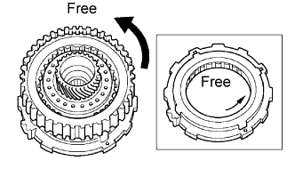
| 11. INSPECT UNDERDRIVE ONE-WAY CLUTCH ASSEMBLY |
Install the underdrive clutch assembly to the one-way clutch.
Check that the underdrive one-way clutch locks when turned clockwise and rotates freely when turned counterclockwise as shown in the illustration.
If the result is not as specified, replace the underdrive one-way clutch.
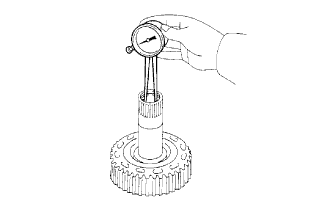
| 12. INSPECT INPUT SHAFT END PLAY |
Using a dial indicator, measure the input shaft end play.
- Standard end play:
- 0.262 to 1.244 mm (0.01 to 0.049 in.)
If the result is not as specified, replace the input shaft or thrust needle roller bearing.