Dtc P0798 Pressure Control Solenoid C Electrical (Shift Solenoid Valve Sl3)
DESCRIPTION
MONITOR DESCRIPTION
WIRING DIAGRAM
INSPECTION PROCEDURE
INSPECT TRANSMISSION WIRE (SHIFT SOLENOID VALVE SL3)
CHECK HARNESS AND CONNECTOR (TRANSMISSION WIRE - ECM)
INSPECT SHIFT SOLENOID VALVE SL3
DTC P0798 Pressure Control Solenoid "C" Electrical (Shift Solenoid Valve SL3) |
DESCRIPTION
Shifting from 1st to 5th is performed in combination with the ON and OFF operation of the shift solenoid valves SL1, SL2, SL3, S4 or SR which are controlled by the ECM. If an open or short circuit occurs in any of the shift solenoid valves, the ECM controls the remaining normal shift solenoid valves to allow the vehicle to be operated safely (RAV4_ACA30 RM000000O8L0BDX.html).DTC No.
| DTC Detection Condition
| Trouble Area
|
P0798
| The ECM checks for an open or short in the shift solenoid valve SL3 circuit while driving and shifting gears (1 trip detection logic)
| - Open or short in shift solenoid valve SL3 circuit
- Shift solenoid valve SL3
- ECM
|
MONITOR DESCRIPTION
The ECM commands gear shifts by turning the shift solenoid valves ON/OFF. When there is an open or short circuit in any shift solenoid valve circuit, the ECM detects the problem and illuminates the MIL and stores the DTC. And the ECM performs the fail-safe function and turns the other normal shift solenoid valves ON/OFF. In case of an open or short circuit, the ECM stops sending current to the circuit (RAV4_ACA30 RM000000O8L0BDX.html).
WIRING DIAGRAM
INSPECTION PROCEDURE
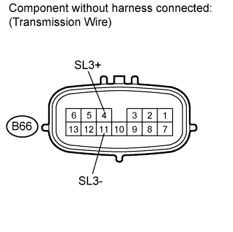
| 1.INSPECT TRANSMISSION WIRE (SHIFT SOLENOID VALVE SL3) |
Disconnect the transmission wire connector.
Measure the resistance according to the value(s) in the table below.
- Standard resistance:
Tester Connection
| Condition
| Specified Condition
|
4 (SL3+) - 11 (SL3-)
| 20°C (68°F)
| 5.0 to 5.6 Ω
|
4 (SL3+) - Body ground
| Always
| 10 kΩ or higher
|
11 (SL3-) - Body ground
| Always
| 10 kΩ or higher
|
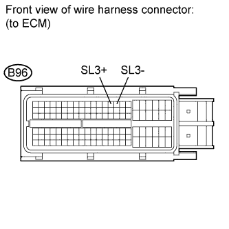
| 2.CHECK HARNESS AND CONNECTOR (TRANSMISSION WIRE - ECM) |
Connect the transmission wire connector.
Disconnect the ECM connector.
Measure the resistance according to the value(s) in the table below.
- Standard resistance:
Tester Connection
| Condition
| Specified Condition
|
B96-14 (SL3+) - B96-15 (SL3-)
| 20°C (68°F)
| 5.0 to 5.6 Ω
|
B96-14 (SL3+) - Body ground
| Always
| 10 kΩ or higher
|
B96-15 (SL3-) - Body ground
| Always
| 10 kΩ or higher
|
| | REPAIR OR REPLACE HARNESS OR CONNECTOR |
|
|
| 3.INSPECT SHIFT SOLENOID VALVE SL3 |
Remove the shift solenoid valve SL3.
Measure the resistance according to the value(s) in the table below.
- Standard resistance:
Tester Connection
| Condition
| Specified Condition
|
1 - 2
| 20°C (68°F)
| 5.0 to 5.6 Ω
|
Connect the battery's positive (+) lead with a 21 W bulb to terminal 2 and the negative (-) lead to terminal 1 of the solenoid valve connector. Then check that the valve moves and makes an operating sound.
- OK:
- Valve moves and makes operating sound.