Dtc B2278 Engine Switch Circuit Malfunction
Engine. Toyota Rav4. Aca30, 33, 38 Gsa33 Zsa30, 35
DESCRIPTION
WIRING DIAGRAM
INSPECTION PROCEDURE
READ VALUE USING INTELLIGENT TESTER (START SWITCH 1 AND 2)
CHECK SWITCH CONDITION (ENGINE SWITCH)
INSPECT ENGINE SWITCH
CHECK HARNESS AND CONNECTOR (ENGINE SWITCH - MAIN BODY ECU AND BODY GROUND)
DTC B2278 Engine Switch Circuit Malfunction |
DESCRIPTION
This DTC is stored when 1) a malfunction is detected between the main body ECU and engine switch; or 2) either of the switches inside the engine switch is malfunctioning.DTC Code
| DTC Detection Condition
| Trouble Area
|
B2278
| Communication is abnormal between the main body ECU and engine switch or the engine switch is defective.
| - Main body ECU
- Engine switch
- Harness or connector
|
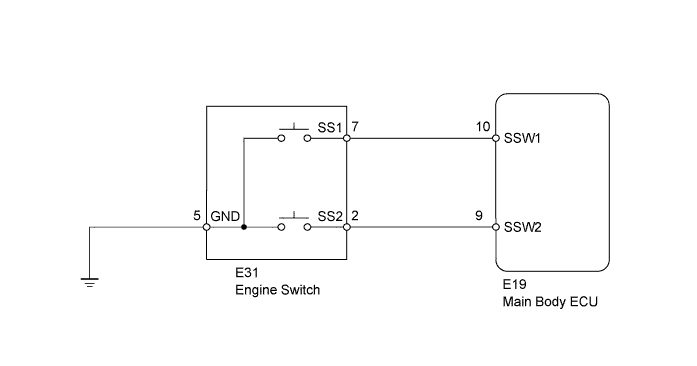
WIRING DIAGRAM
INSPECTION PROCEDURE
| 1.READ VALUE USING INTELLIGENT TESTER (START SWITCH 1 AND 2) |
Connect the intelligent tester to the DLC3.
Turn the engine switch on (IG) and turn the intelligent tester on.
Enter the following menus: Body / Main Body / Data List.
Read the value displayed on the intelligent tester.
Main BodyTester Display
| Measurement Item/Range
| Normal Condition
| Diagnostic Note
|
Start Switch1
| Start Switch 1/ON or OFF
| ON: Engine switch on (IG)
OFF: Engine switch off
| -
|
Start Switch2
| Start Switch 2/ON or OFF
| ON: Engine switch on (IG)
OFF: Engine switch off
| -
|
- OK:
- When the engine switch is turned on (IG), ON appears on the intelligent tester screen.
| 2.CHECK SWITCH CONDITION (ENGINE SWITCH) |
Make sure that the electrical key is inside the cabin.
With the shift lever in P (except M/T), check that the power source mode changes as shown below each tine the engine switch is pushed.
- OK:
- off → on (ACC) → on (IG) → off
Remove the engine switch (RAV4_ACA30 RM000002MDV00OX.html).
Measure the resistance according to the value(s) in the table below.
- Standard Resistance:
Tester Connection
| Switch Condition
| Specified Condition
|
7 (SS1) - 5 (GND)
| Pushed
| Below 1 Ω
|
2 (SS2) - 5 (GND)
| Pushed
| Below 1 Ω
|
7 (SS1) - 5 (GND)
| Not pushed
| 10 kΩ or higher
|
2 (SS2) - 5 (GND)
| Not pushed
| 10 kΩ or higher
|
| 4.CHECK HARNESS AND CONNECTOR (ENGINE SWITCH - MAIN BODY ECU AND BODY GROUND) |
Disconnect the E31 engine switch connector.
Disconnect the E19 main body ECU connector.
Measure the resistance according to the value(s) in the table below.
- Standard Resistance:
Tester Connection
| Condition
| Specified Condition
|
E31-7 (SS1) - E19-10 (SSW1)
| Always
| Below 1 Ω
|
E31-2 (SS2) - E19-9 (SSW2)
| Always
| Below 1 Ω
|
E31-5 (GND) - Body ground
| Always
| Below 1 Ω
|
E31-7 (SS1) or E19-10 (SSW1) - Body ground
| Always
| 10 kΩ or higher
|
E31-2 (SS2) or E19-9 (SSW2) - Body ground
| Always
| 10 kΩ or higher
|
| | REPAIR OR REPLACE HARNESS OR CONNECTOR |
|
|
| OK |
|
|
|
| REPLACE MAIN BODY ECU (INSTRUMENT PANEL JUNCTION BLOCK) |
|