Intake System System Diagram
Engine. Toyota Rav4. Aca30, 33, 38 Gsa33 Zsa30, 35
AIR INTAKE CONTROL SYSTEM DIAGRAM
ACOUSTIC CONTROL INDUCTION SYSTEM DIAGRAM
INTAKE SYSTEM WIRING DIAGRAM
Intake System -- System Diagram |
| AIR INTAKE CONTROL SYSTEM DIAGRAM |
- The system has a dual path design for air intake. An air intake control valve and actuator control the air flow path.
- When the engine is operating in the low to medium speed range, this control operates the air intake control valve to close one side of the air cleaner inlet.
- When the engine is operating in the high speed range, this control operates the air intake control valve to open both sides of the air cleaner inlet.
| ACOUSTIC CONTROL INDUCTION SYSTEM DIAGRAM |
- The ACIS is realized by using a bulkhead to divide the intake manifold into 2 stages, with the intake air control valve in the bulkhead being opened and closed to vary the effective length of the intake manifold in accordance with the engine speed and throttle valve opening angle. This increases the power output in all ranges from low to high speed.
- When the intake control valve closes:
While the engine is running at medium speed under high load, the ECM controls the actuator to close the control valve. As a result, the effective length of the intake manifold is lengthened and the intake efficiency, in the medium speed range, is improved due to the dynamic effect of the intake air, thereby increasing power output.
- When the intake control valve opens:
Under any condition except when the engine is running at medium speed under high load, the ECM controls the actuator to open the control valve. When the control valve is open, the effective length of the intake air chamber is shortened and peak intake efficiency is shifted to the low to high engine speed range, thus providing greater output at low to high engine speeds.
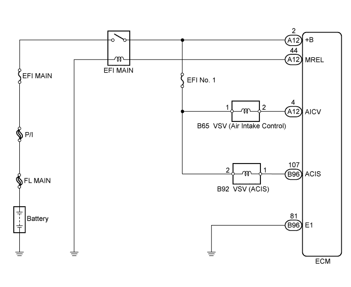
| INTAKE SYSTEM WIRING DIAGRAM |