Engine Unit -- Replacement |
| 1. REPLACE SPARK PLUG TUBE GASKET |
Pry up the claws of the ventilation baffle plate.
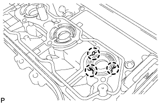 |
Using a screwdriver with its tip taped and a hammer, tap out the 6 spark plug tube gaskets.
 |
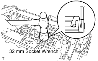
Using a 32 mm socket wrench, tap in 6 new spark plug tube gaskets to the head covers.
- NOTICE:
- Keep the lip free from foreign matter.
- Do not tap on the oil seal at an angle.
 |
Return the claws of the ventilation baffle plate to its original positions.
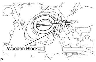
| 2. REPLACE TIMING CHAIN COVER OIL SEAL |
Using a screwdriver, pry out the oil seal.
- HINT:
- Tape the screwdriver tip before use.
- NOTICE:
- Do not damage the surface of the oil seal press fit hole.
 |
Using SST and a hammer, tap in a new oil seal until its surface is flush with the timing chain cover edge.
- SST
- 09316-60011(09316-00011)
- NOTICE:
- Keep the lip free from foreign matter.
- Do not tap the oil seal at an angle.
- Make sure that the oil seal edge does not stick out of the timing chain case.
 |
Apply MP grease to the lip of the oil seal.
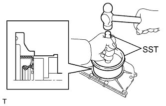
| 3. REPLACE ENGINE REAR OIL SEAL |
Place the oil seal retainer on wooden blocks.
 |
Using a screwdriver and a hammer, tap out the oil seal.
Using SST, tap in a new oil seal until its surface is flush with the oil seal retainer edge.
- SST
- 09223-15030
- NOTICE:
- Keep the lip free from foreign matter.
- Do not tap on the oil seal at an angle.
 |
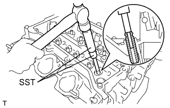
| 4. REPLACE INTAKE VALVE GUIDE BUSH |
Heat the cylinder head to approximately 80 to 100°C (176 to 212°F).
Place the cylinder head on wooden blocks.
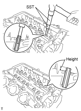
Using SST and a hammer, tap out the valve guide bush.
- SST
- 09201-10000(09201-01050)
09950-70010(09951-07100)
 |
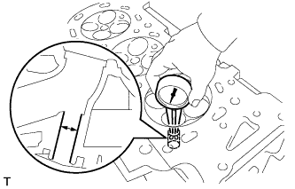
Using a caliper gauge, measure the bush bore diameter of the cylinder head.
- Standard cylinder bore diameter:
- 10.285 to 10.306 mm (0.4049 to 0.4057 in.)
 |
Select a new guide bush (STD or O/S 0.05).
- Standard bush bore diameter:
Bush Size Specified Condition Use STD 10.335 to 10.356 mm (0.4069 to 0.4077 in.) Use O/S 0.05 10.285 to 10.306 mm (0.4049 to 0.4057 in.)
- HINT:
- If the bush bore diameter of the cylinder head is greater than 10.344 mm (0.4072 in.), machine the bush bore diameter to between 10.383 and 10.394 mm (0.4088 and 0.4092 in.).
- If the bush bore diameter of the cylinder head is greater than 10.344 mm (0.4072 in.), replace the cylinder head.
Heat the cylinder head to approximately 80 to 100°C (176 to 212°F).
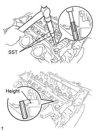
Using SST and a hammer, tap in a new guide bush to the specified protrusion height.
- Standard protrusion height:
- 9.1 to 9.9 mm (0.3582 to 0.3900 in.)
- SST
- 09201-10000(09201-01050)
09950-70010(09951-07100)
 |
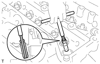
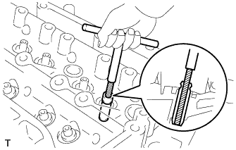
Using a sharp 5.5 mm reamer, ream the guide bush to obtain the standard specified clearance between the guide bush and valve stem.
 |
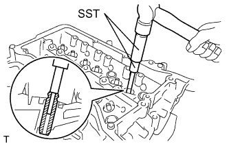
| 5. REPLACE EXHAUST VALVE GUIDE BUSH |
Heat the cylinder head to approximately 80 to 100°C (176 to 212°F).
Place the cylinder head on wooden blocks.
Using SST and a hammer, tap out the valve guide bush.
- SST
- 09201-10000(09201-01050)
09950-70010(09951-07100)
 |
Using a caliper gauge, measure the bush bore diameter of the cylinder head.
- Standard cylinder bore diameter:
- 10.285 to 10.306 mm (0.4049 to 0.4057 in.)
 |
Select a new guide bush (STD or O/S 0.05).
- Standard bush bore diameter:
Bush Size Specified Condition Use STD 10.335 to 10.356 mm (0.4069 to 0.4077 in.) Use O/S 0.05 10.285 to 10.306 mm (0.4049 to 0.4057 in.)
- HINT:
- If the bush bore diameter of the cylinder head is greater than 10.344 mm (0.4072 in.), machine the bush bore diameter to between 10.383 and 10.394 mm (0.4088 and 0.4092 in.).
- If the bush bore diameter of the cylinder head is greater than 10.344 mm (0.4072 in.), replace the cylinder head.
Heat the cylinder head to approximately 80 to 100°C (176 to 212°F).
Using SST and a hammer, tap in a new guide bush to the specified protrusion height.
- SST
- 09201-10000(09201-01050)
09950-70010(09951-07100)
- Standard protrusion height:
- 9.30 to 9.70 mm (0.3661 to 0.3819 in.)
 |
Using a sharp 5.5 mm reamer, ream the guide bush to obtain the standard specified clearance between the guide bush and valve stem.
 |
| 6. REPLACE CYLINDER BLOCK STUD BOLT |
- NOTICE:
- If a stud bolt is deformed or the threads are damaged, replace it.
Remove the stud bolts.

Using an E8 "TORX" socket wrench, install the stud bolts.
- Torque:
- 10 N*m{102 kgf*cm, 7 ft.*lbf}
| 7. REPLACE CYLINDER BLOCK STRAIGHT PIN |
- NOTICE:
- It is not necessary to remove the straight pin unless it is being replaced.
Remove the straight pin.

Using a plastic-faced hammer, tap in new straight pins to the cylinder block.
- Standard protrusion:
Item Specified Condition Pin A 23 mm (0.91 in.) Pin B 6 mm (0.24 in.) Pin C 11 mm (0.43 in.) Pin D 9 mm (0.35 in.)
| 8. REPLACE CYLINDER HEAD RING PIN |
- NOTICE:
- It is not necessary to remove the ring pin unless it is being replaced.
Remove the ring pins.
 |
Using a plastic-faced hammer, tap in a new ring pin until the pin stops.
| 9. REPLACE CYLINDER HEAD STUD BOLT |
- NOTICE:
- If a stud bolt is deformed or the threads are damaged, replace it.
Remove the stud bolts.
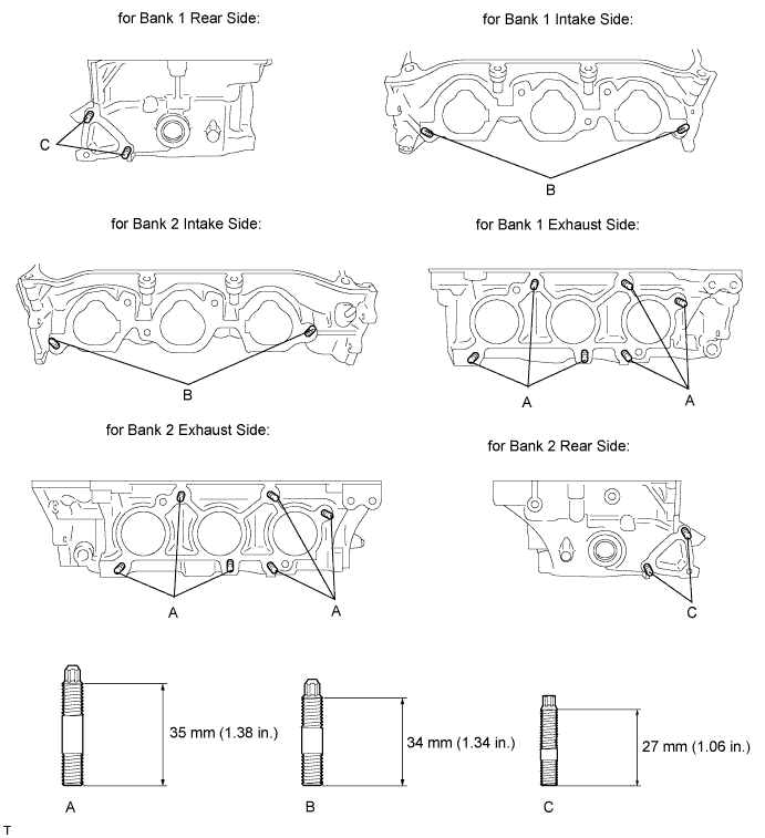
Using E6 and E8 "TORX" socket wrenches, install the stud bolts.
- Torque:
- 10 N*m{102 kgf*cm, 7 ft.*lbf}for stud bolts A and B
- 4.0 N*m{41 kgf*cm, 35 in.*lbf}for stud bolt C
| 10. REPLACE CYLINDER HEAD SET STRAIGHT PIN |
- NOTICE:
- It is not necessary to remove the straight pin unless it is being replaced.
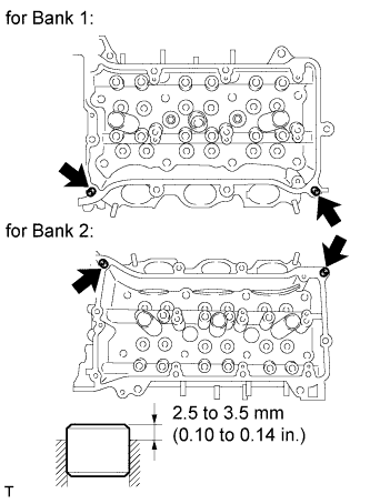
Using a plastic-faced hammer, tap in a new straight pin as shown in the illustration.
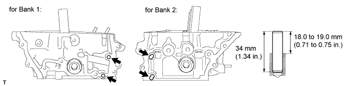
- Standard protrusion height:
- 18.0 to 19.0 mm (0.71 to 0.75 in.)