REMOVE TRANSMISSION CONTROL CABLE ASSEMBLY (for Automatic Transaxle)
REMOVE TRANSMISSION CONTROL CABLE ASSEMBLY (for Manual Transaxle)
REMOVE CLUTCH RELEASE CYLINDER ASSEMBLY (for Manual Transaxle)
REMOVE COOLER COMPRESSOR ASSEMBLY (w/ Air Conditioning System)
REMOVE TORQUE CONVERTER CLUTCH ASSEMBLY (for Automatic Transaxle)
Engine Assembly -- Removal |
| 1. DISCHARGE FUEL SYSTEM PRESSURE |
- CAUTION:
- DISCHARGE FUEL SYSTEM PRESSURE procedures must be performed before disconnecting any part of the fuel system.
- After performing the DISCHARGE FUEL SYSTEM PRESSURE procedures, pressure will remain in the fuel line. When disconnecting the fuel line, place a cloth or equivalent over fittings to reduce the risk of fuel spray.
Remove the console box (RAV4_ACA30 RM000001RHJ00GX_01_0039.html).
Disconnect the connector.
 |
Start the engine. After the engine has stopped, turn the ignition switch off.
- HINT:
- DTC P0171 (system too lean) may be set.
Check that the engine does not start.
Remove the fuel tank cap, and let the air out of the fuel tank.
Connect the connector.
|
Install the console box (RAV4_ACA30 RM000001RHG00HX_01_0010.html).
| 2. DISCONNECT CABLE FROM NEGATIVE BATTERY TERMINAL |
- CAUTION:
- Wait at least 90 seconds after disconnecting the cable from the negative (-) battery terminal to prevent airbag and seat belt pretensioner activation.
| 3. REMOVE HOOD SUB-ASSEMBLY |
Remove the engine hood (RAV4_ACA30 RM00000161Z00KX_01_0006.html).
| 4. REMOVE RADIATOR SUPPORT OPENING COVER |
| 5. REMOVE BATTERY CLAMP SUB-ASSEMBLY |
Loosen the bolt and nut, and remove the battery clamp.
| 6. REMOVE BATTERY |
| 7. REMOVE BATTERY TRAY |
| 8. REMOVE FRONT WHEEL |
| 9. REMOVE NO. 1 ENGINE UNDER COVER |
| 10. REMOVE NO. 2 ENGINE UNDER COVER |
| 11. REMOVE FRONT FENDER APRON RH |
| 12. REMOVE NO. 1 ENGINE COVER |
Remove the 2 nuts and cover.
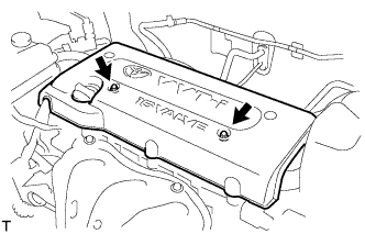 |
| 13. DRAIN ENGINE COOLANT |
Loosen the radiator drain cock plug.
- HINT:
- Collect the coolant in a container and dispose of it according to the regulations in your area.
Remove the radiator reservoir cap.
- CAUTION:
- Do not remove the radiator reservoir cap while the engine and radiator are still hot. Pressurized, hot engine coolant and steam may be released and cause serious burns.
Loosen the cylinder block drain cock plug.

| 14. DRAIN AUTOMATIC TRANSAXLE FLUID |
Remove the drain plug and gasket, and drain ATF.
Install a new gasket and the drain plug.
- Torque:
- 47 N*m{479 kgf*cm, 35 ft.*lbf}
| 15. DRAIN MANUAL TRANSAXLE OIL |
Remove the filler plug and gasket.
Remove the drain plug and gasket, and drain the oil.
Install a new gasket and the drain plug.
- Torque:
- 49 N*m{500 kgf*cm, 36 ft.*lbf}
| 16. REMOVE RADIATOR ASSEMBLY |
Remove the radiator (RAV4_ACA30 RM000001X9G00LX.html).
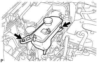
| 17. REMOVE RADIATOR RESERVOIR TANK |
Remove the 2 bolts and radiator reservoir.
 |
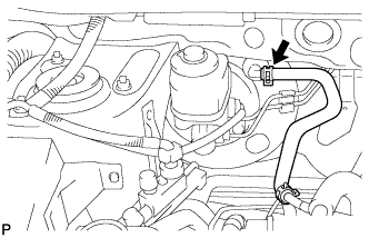
| 18. REMOVE PURGE VSV |
Disconnect the purge VSV connector.
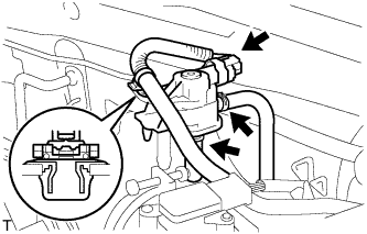 |
Disconnect the wire harness clamp.
Disconnect the 2 purge line hoses from the purge VSV.
Remove the purge VSV from the air cleaner hose.
| 19. REMOVE AIR CLEANER CAP |
Disconnect the mass air flow meter connector.
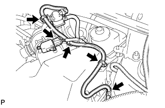 |
Disconnect the purge VSV connector.
Disconnect the 4 wire harness clamps.
Disconnect the No. 2 ventilation hose from the air cleaner hose.
 |
Disconnect the purge line hose from the clamp.
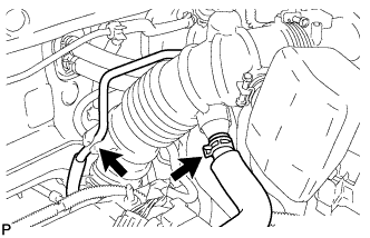
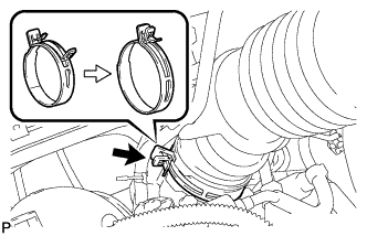
Lock the No. 1 air cleaner hose clamp, and then disconnect the No. 1 air cleaner hose from the throttle body.
 |
Unfasten the 2 hook clamps, and then remove the air cleaner cap.
 |
Remove the air cleaner filter element from the air cleaner case.
| 20. REMOVE AIR CLEANER CASE |
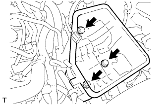
Remove the 3 bolts from the air cleaner case.
 |
Disconnect the case from the No. 1 air cleaner inlet.
| 21. REMOVE FRONT BATTERY CARRIER |
Disconnect the 2 clamps of the engine wire.
 |
Remove the 4 bolts and front battery carrier.
| 22. REMOVE BATTERY BRACKET REINFORCEMENT |
Remove the 2 bolts and battery bracket reinforcement.
 |
| 23. REMOVE BATTERY CARRIER BRACKET |
Remove the 2 bolts, nut and battery carrier bracket.
 |
| 24. DISCONNECT UNION TO CONNECTOR TUBE HOSE (for LHD) |
Disconnect the 2 union to connector tube hoses from the booster vacuum tube.
 |
| 25. DISCONNECT UNION TO CONNECTOR TUBE HOSE (for RHD) |
Disconnect the union to connector tube hose from the booster vacuum tube.
 |
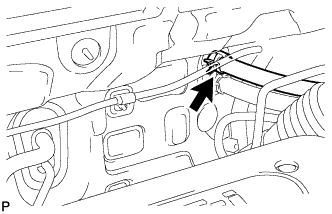
| 26. DISCONNECT HEATER WATER INLET HOSE |
Disconnect the heater water inlet hose from the heater unit.
 |
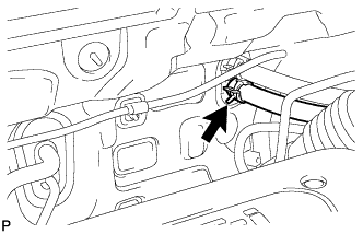
| 27. DISCONNECT HEATER WATER OUTLET HOSE |
Disconnect the heater water outlet hose from the heater unit.
 |
| 28. DISCONNECT FUEL TUBE |
 |
- NOTICE:
- Do not forcibly bend and twist the fuel main tube.
Remove the fuel tube from the fuel hose clamp.
Remove the fuel pipe clamp.
Wipe off any dirt on the fuel tube connector.
Hold the fuel tube connector, and then install the SST.
- SST
- 09268-21010
Turn the SST to align the retainer inside the fuel tube connector with the chamfered part of the SST.
Insert the SST into the fuel tube and hold it. Then push the fuel tube connector toward the SST side.
Mount the retainer of the fuel tube connector onto the chamfered part of the SST.
Slide the SST and fuel tube connector together towards the fuel tube until they make a "click" sound, and then disconnect the fuel tube.
 |
Drain the fuel remaining inside the fuel tube.
Cover the fuel tube and fuel pipe with a plastic bag to protect the disconnected part.
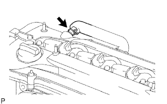
| 29. DISCONNECT NO. 2 VENTILATION HOSE |
Disconnect the No. 2 ventilation hose from the ventilation valve.
 |
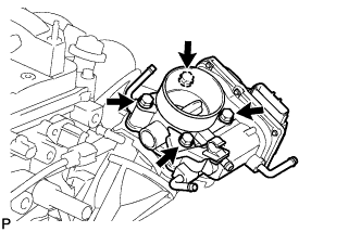
| 30. REMOVE THROTTLE BODY |
Disconnect the purge line hose from the throttle body.
 |
Disconnect the water by-pass hose from the throttle body.
Disconnect the No. 2 water by-pass hose from the throttle body.
for Type A:
Disconnect the No. 1 throttle body hose from the throttle body.
Disconnect the throttle position sensor and control motor connector.
Disconnect the wire harness clamp.
Disconnect the fuel tube from the clamp.
Remove the 4 bolts, and then remove the fuel pipe support and throttle body.
 |
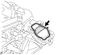
Remove the gasket from the intake manifold.
 |
| 31. REMOVE FUEL DELIVERY PIPE SUB-ASSEMBLY |
Remove the 2 wire harness clamps.
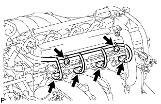 |
Disconnect the 4 fuel injector connectors.
Remove the 2 bolts and then pull out the fuel delivery pipe together with the 4 fuel injectors.
- NOTICE:
- Be careful not to drop the fuel injectors when removing the fuel delivery pipe.
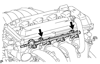 |
Remove the 2 delivery pipe spacers from the cylinder head.
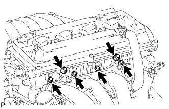 |
Remove the 4 insulators from the cylinder head.
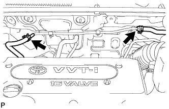
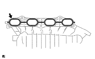
| 32. REMOVE INTAKE MANIFOLD |
Disconnect the union to check valve hose from the brake booster.
Disconnect the camshaft timing oil control valve connector.
 |
Remove the wire harness clamp.
Remove the union to check valve hose from the vacuum hose clamp.
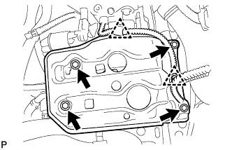
Remove the 5 bolts, 2 nuts and intake manifold.
Remove the gasket from the intake manifold.
 |
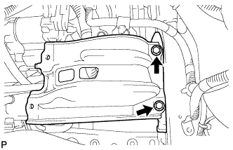
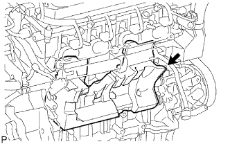
| 33. REMOVE INTAKE MANIFOLD INSULATOR |
Remove the intake manifold insulator from the cylinder block.
 |
| 34. REMOVE TRANSMISSION CONTROL CABLE ASSEMBLY (for Automatic Transaxle) |
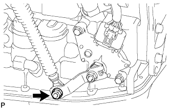 |
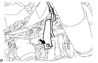
Remove the nut and disconnect the control cable from the control shaft lever.
Remove the clip and disconnect the control cable from the control cable bracket.
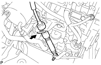 |
Disconnect the control cable from the control cable support.
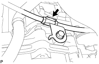 |
Remove the bolt and disconnect the clamp of the control cable.
 |
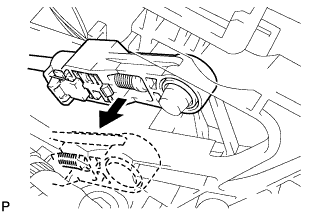
Disconnect the control cable from the shift lever.
 |
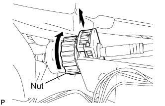
Turn the nut and disconnect the control cable from the shift lever retainer.
 |
Remove the 2 bolts and control cable.
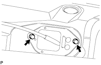 |
| 35. REMOVE TRANSMISSION CONTROL CABLE ASSEMBLY (for Manual Transaxle) |
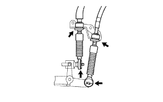 |
Removal the 2 clips and washers, and disconnect the top ends of the control cable from the transaxle.
Remove the 2 clips and disconnect the control cable bracket.
Remove the 2 bolts from the retainer.
 |
Pull out the control cable from the floor.
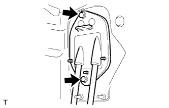
| 36. REMOVE CLUTCH RELEASE CYLINDER ASSEMBLY (for Manual Transaxle) |
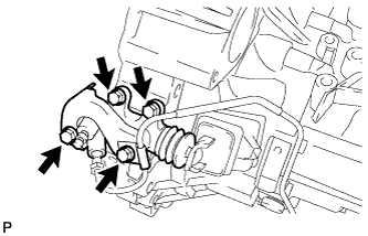 |
Remove the 4 bolts and clutch release cylinder.
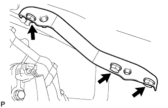
| 37. REMOVE FRONT SUSPENSION MEMBER REINFORCEMENT RH |
Remove the 4 bolts and reinforcement RH.
| 38. REMOVE FAN & GENERATOR V BELT |
Using SST 19 mm socket wrench, loosen the V-ribbed belt tensioner arm clockwise, then remove the fan and generator V belt.
- SST
- 09216-42010
- NOTICE:
- Be sure to connect SST and the tools so that they are in line during use.
- When retracting the tensioner, turn it clockwise slowly for 3 seconds or more. Do not apply force rapidly.
- After the tensioner is fully retracted, do not apply force any more than necessary.
 |
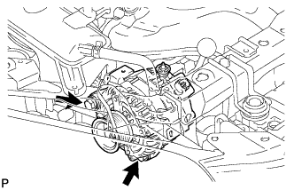
| 39. REMOVE GENERATOR ASSEMBLY |
Disconnect the generator connector.
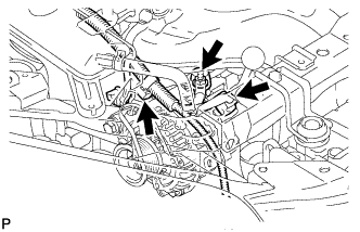 |
Remove the terminal cap.
Remove the nut and disconnect the generator wire.
Remove the bolt and wire harness clamp bracket.
Remove the wire harness clamp.
Remove the 2 bolts and generator.
 |
| 40. REMOVE COOLER COMPRESSOR ASSEMBLY (w/ Air Conditioning System) |
- HINT:
- Disconnect the compressor together with the low-pressure and high-pressure hoses, then secure it to the vehicle side using rope.
| 41. REMOVE ECM |
Remove the ECM (RAV4_ACA30 RM0000017UO01FX_01_0003.html).
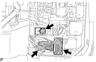
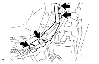
| 42. DISCONNECT ENGINE WIRE |
Remove the engine room relay block cover.
Remove the nut and disconnect the 2 engine wire connectors.
 |
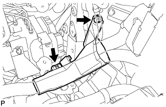
Remove the bolt and engine wire cover.
Then disconnect the engine wire from the engine wire cover clamp.
 |
Disconnect the ground cable connector.
 |
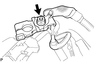
Remove the nut from the positive (+) battery terminal to disconnect the engine wire.
 |
Disconnect the ground cable from the clamp located near the starter.
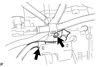 |
Remove the bolt and ground cable located near the starter.
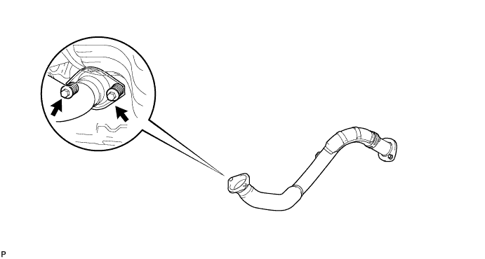
| 43. REMOVE FRONT EXHAUST PIPE ASSEMBLY |
Remove the 2 bolts, 2 compression springs and front exhaust pipe.
Remove the gasket from the exhaust manifold.
| 44. REMOVE FRONT DRIVE SHAFT ASSEMBLY |
Remove the front drive shaft (RAV4_ACA30 RM00000226Q008X.html).
| 45. REMOVE PROPELLER SHAFT WITH CENTER BEARING SHAFT ASSEMBLY |
Remove the 2 bolts and 2 adjusting washers, and disconnect the propeller with center bearing shaft.
- NOTICE:
- During the removal, do not exert excessive force on the universal joint.
- When removing, transporting or storing the propeller with center bearing shaft assembly, do not allow the No. 2 joint angle to exceed 20°.
 |
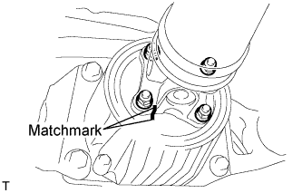
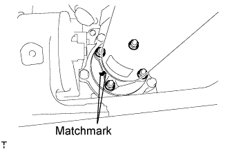
Place matchmarks on the differential carrier and propeller shaft.
 |
Remove the 4 nuts and 4 washers, and disconnect the propeller shaft and differential carrier.
Place matchmarks on the transfer and propeller shaft.
 |
Remove the 4 nuts and 4 washers, and disconnect the propeller shaft from the transfer.
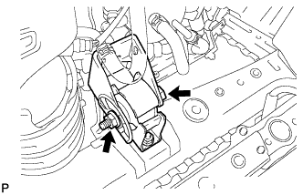
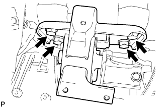
| 46. REMOVE ENGINE MOUNTING INSULATOR FR |
Remove the through bolt and nut.
 |
Remove the 2 bolts and engine mounting insulator FR.
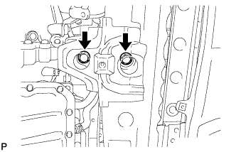 |
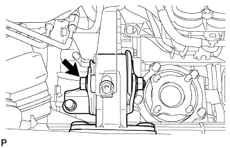
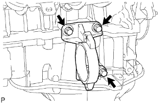
| 47. REMOVE ENGINE MOUNTING INSULATOR RR |
Remove the through bolt.
 |
Remove the 2 nuts, 2 bolts and engine mounting insulator RR.
 |
| 48. REMOVE ENGINE ASSEMBLY WITH TRANSAXLE |
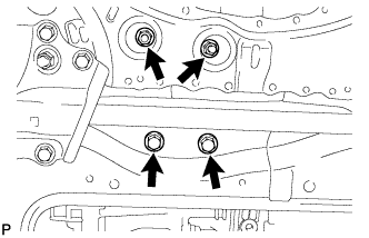
Install the No. 1 and No. 2 engine hangers with the bolts as shown in the illustration.
- Part No.:
Item Part No. No. 1 engine hanger 12281-28010 No. 2 engine hanger 12282-28010 Bolt 91512-61020
- Torque:
- 38 N*m{387 kgf*cm, 28 ft.*lbf}
 |
Attach the sling device to the engine hangers and chain block.
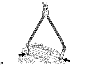 |
Carefully remove the engine with transaxle from the vehicle.
| 49. REMOVE ENGINE MOUNTING INSULATOR RH |
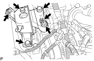
Remove the 2 nuts, 4 bolts and engine mounting insulator RH.
 |
| 50. REMOVE ENGINE MOUNTING INSULATOR LH |
Remove the through bolt and nut.
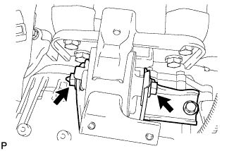 |
Remove the 4 bolts and engine mounting insulator LH.
 |
| 51. REMOVE DRIVE SHAFT BEARING BRACKET |
Remove the 3 bolts and bracket.
 |
| 52. REMOVE TRANSFER ASSEMBLY |
except K111F:
Remove the 6 nuts, 2 bolts and transfer from the transaxle.
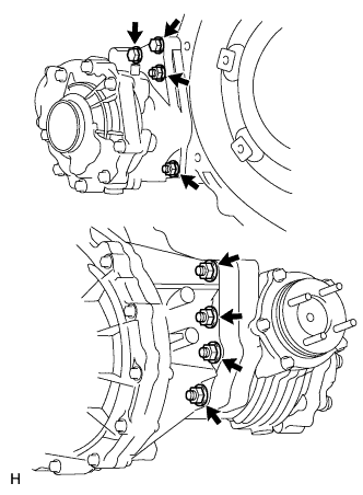 |
for K111F:
Remove the 6 nuts and transfer from the transaxle.
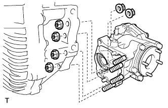 |
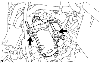
| 53. REMOVE STARTER ASSEMBLY |
Disconnect the starter connector.
 |
Open the terminal cap, remove the nut and disconnect the starter wire.
Remove the 2 bolts and starter.
 |
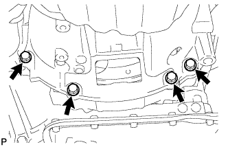
| 54. REMOVE AUTOMATIC TRANSAXLE ASSEMBLY |
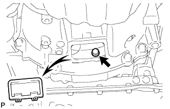 |
Remove the flywheel housing under cover.
Turn the crankshaft to gain access and remove the 6 bolts while holding the crankshaft pulley bolt with a wrench.
Remove the 4 lower side mounting bolts.
 |
Remove the 5 upper side mounting bolts.
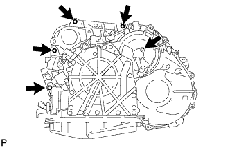 |
Separate and remove the automatic transaxle.
| 55. REMOVE TORQUE CONVERTER CLUTCH ASSEMBLY (for Automatic Transaxle) |
| 56. REMOVE DRIVE PLATE SUB-ASSEMBLY (for Automatic Transaxle) |
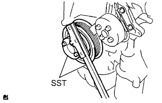
Using SST, hold the crankshaft.
- SST
- 09213-54015(91651-60855)
09330-00021
 |
Remove the 8 bolts, rear spacer, drive plate and front spacer.
 |
| 57. REMOVE FLYWHEEL HOUSING UNDER COVER (for Manual Transaxle) |
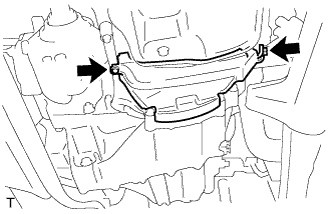 |
Remove the 2 bolts and insulator from the stiffener plate.
| 58. REMOVE STIFFENER PLATE LH (for Manual Transaxle) |
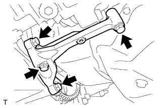 |
Remove the 4 bolts and stiffener plate from the engine and transaxle assembly.
| 59. REMOVE STIFFENER PLATE RH (for Manual Transaxle) |
 |
Remove the 4 bolts and stiffener plate from the engine and transaxle assembly.
| 60. REMOVE MANUAL TRANSAXLE ASSEMBLY |
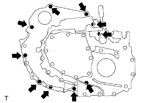 |
Remove the 10 bolts.
Separate and remove the transaxle from the engine.
| 61. REMOVE CLUTCH COVER ASSEMBLY (for Manual Transaxle) |
 |
Put matchmarks on the clutch cover assembly and flywheel sub-assembly.
Text in Illustration *1 Matchmark
Loosen each set bolt one turn at a time in the order shown in the illustration until the spring tension is released.
Remove the set bolts and pull off the clutch cover assembly.
- NOTICE:
- Do not drop the clutch disc assembly.
| 62. REMOVE CLUTCH DISC ASSEMBLY (for Manual Transaxle) |
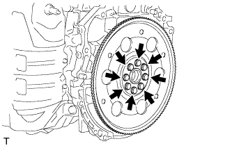
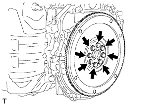
| 63. REMOVE FLYWHEEL SUB-ASSEMBLY (for Manual Transaxle) |
Using SST, hold the crankshaft.
- SST
- 09213-54015(91651-60855)
09330-00021
|
Remove the 8 bolts and flywheel.
 |