Engine. Toyota Rav4. Aca30, 33, 38 Gsa33 Zsa30, 35
3Zr-Fae Engine Control System. Toyota Rav4. Aca30, 33, 38 Gsa33 Zsa30, 35
Integration Relay -- On-Vehicle Inspection |
| 1. DISCONNECT CABLE FROM NEGATIVE BATTERY TERMINAL |
- NOTICE:
- w/ Navigation System (for HDD):
- After the ignition switch is turned off, the HDD navigation system requires approximately a minute to record various types of memory and settings. As a result, after turning the ignition switch off, wait a minute or more before disconnecting the cable from the negative (-) battery terminal.
| 2. INSPECT INTEGRATION RELAY (EFI MAIN) |
- NOTICE:
- The EFI relay is built into the integration relay (unit A: EFI MAIN).
- Some relays are built into the integration relay. The integration relay cannot be disassembled. If there is a malfunction in the circuit of the integration relay, replace the integration relay.
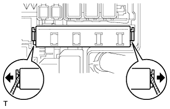
Using a screwdriver, detach the 2 claws and disconnect the integration relay from the No. 1 engine room junction block.
- HINT:
- Tape the screwdriver tip before use.
 |
Disconnect the 3 connectors from the integration relay.
Measure the resistance of the EFI MAIN fuse.
Remove the EFI MAIN fuse from the integration relay.
Measure the resistance according to the value(s) in the table below.
- Standard Resistance:
Tester Connection Condition Specified Condition EFI MAIN fuse Always Below 1 Ω
Install the EFI MAIN fuse to the integration relay.
 |
Measure the resistance of the EFI MAIN relay.
Measure the resistance according to the value(s) in the table below.
- Standard Resistance:
Tester Connection Condition Specified Condition 1A-4 - 1C-1 Battery voltage not applied to terminals 1A-3 and 1A-2 10 kΩ or higher 1A-4 - 1A-1 1A-4 - 1C-1 Battery voltage applied to terminals 1A-3 and 1A-2 Below 1 Ω 1A-4 - 1A-1
| 3. CONNECT CABLE TO NEGATIVE BATTERY TERMINAL |