Terminal No. (Symbol)
| Wiring Color
| Terminal Description
| Condition
| Specified Condition
|
A12-20 (BATT) - B32-105 (E1)
| W - BR
| Battery (for measuring battery voltage and for ECM memory)
| Always
| 11 to 14 V
|
A12-2 (+B) - B32-105 (E1)
| B - BR
| Power source of ECM
| Ignition switch ON
| 11 to 14 V
|
A12-1 (+B2) - B32-105 (E1)
| B - BR
| Power source of ECM
| Ignition switch ON
| 11 to 14 V
|
A12-3 (+BM) - B32-105 (E1)
| LG - BR
| Power source of throttle actuator
| Always
| 11 to 14 V
|
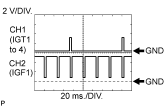
B32-109 (IGT1) - B32-105 (E1)
| R - BR
| Ignition coil
(ignition signal)
| Idling with warm engine
| Pulse generation
(See waveform 1)
|
B32-108 (IGT2) - B32-105 (E1)
| P - BR
|
B32-107 (IGT3) - B32-105 (E1)
| G - BR
|
B32-106 (IGT4) - B32-105 (E1)
| L - BR
|
B32-82 (IGF1) - B32-105 (E1)
| W - BR
| Ignition coil
(ignition confirmation signal)
| Ignition switch ON
| 4.5 to 5.5 V
|
Idling with warm engine
| Pulse generation
(See waveform 1)
|
B32-93 (NE+) - B32-117 (NE-)
| W - B
| Crankshaft position sensor
| Idling with warm engine
| Pulse generation
(See waveform 2)
|
B32-94 (G2+) - B32-118 (G2-)
| B - R
| Variable valve timing (VVT) sensor (intake side)
| Idling with warm engine
| Pulse generation
(See waveform 2)
|
B32-86 (#10) - B32-46 (E01)
| L - W-B
| Injector
| Ignition switch ON
| 11 to 14 V
|
B32-85 (#20) - B32-46 (E01)
| G - W-B
| Idling with warm engine
| Pulse generation
(See waveform 3)
|
B32-84 (#30) - B32-46 (E01)
| B - W-B
|
B32-83 (#40) - B32-46 (E01)
| W - W-B
|
B32-104 (HA1A) - B32-41 (E04)
| L - W-B
| Air fuel ratio sensor heater (sensor 1)
| Ignition switch ON
| 11 to 14 V
|
Idling before air fuel ratio sensor warms up
| Pulse generation
(See waveform 15)
|
B32-103 (A1A+) - B32-105 (E1)
| G - BR
| Air fuel ratio sensor (sensor 1)
| Ignition switch ON
| 3.3 V*1
|
B32-126 (A1A-) - B32-105 (E1)
| R - BR
| Air fuel ratio sensor (sensor 1)
| Ignition switch ON
| 3.0 V*1
|
B32-63 (HT1B) - B32-81 (E03)
| R - W-B
| Heated oxygen sensor heater (sensor 2)
| Ignition switch ON
| 11 to 14 V
|
Idling
| Below 3.0 V
|
B32-80 (OX1B) - B32-79 (O1B-)
| W - B
| Heated oxygen sensor (sensor 2)
| Engine speed maintained at 2500 rpm for 2 minutes after warming up sensor
| Pulse generation
(See waveform 4)
|
B32-110 (KNK1) - B32-111 (EKNK)
| B - W
| Knock sensor
| Engine speed maintained at 4000 rpm after warming up engine
| Pulse generation
(See waveform 5)
|
A12-38 (SPD) - B32-105 (E1)
| V - BR
| Speed signal from combination meter
| Vehicle being driven at approximately 20 km/h (12 mph)
| Pulse generation
(See waveform 6)
|
B32-64 (THW) - B32-65 (ETHW)
| GR - BR
| Engine coolant temperature sensor
| Idling, engine coolant temperature 80°C (176°F)
| 0.2 to 1.0 V
|
B32-87 (THA) - B32-88 (ETHA)
| W - BR
| Intake air temperature sensor
| Idling, intake air temperature 20°C (68°F)
| 0.5 to 3.4 V
|
B32-69 (VG) - B32-92 (E2G)
| R - LG
| Mass air flow meter
| Idling, shift lever in P or N (for CVT) or neutral (for Manual Transaxle), air conditioner OFF
| 0.5 to 3.0 V
|
A12-24 (W) - B32-105 (E1)
| R - BR
| MIL
| Ignition switch ON (MIL goes off)
| Below 3.0 V
|
Idling
| 11 to 14 V
|
A12-48 (STA) - B32-105 (E1)
| LG - BR
| Starter signal
| Cranking
| 5.5 V or higher
|
B32-113 (VTA1) - B32-90 (ETA)
| G - BR
| Throttle position sensor (for engine control)
| Ignition switch ON, throttle valve fully closed
| 0.5 to 1.1 V
|
Ignition switch ON, throttle valve fully open
| 3.2 to 4.8 V
|
B32-112 (VTA2) - B32-90 (ETA)
| L - BR
| Throttle position sensor (for sensor malfunction detection)
| Ignition switch ON, throttle valve fully closed
| 2.1 to 3.1 V
|
Ignition switch ON, throttle valve fully open
| 4.6 to 5.0 V
|
B32-89 (VCTA) - B32-90 (ETA)
| Y - BR
| Power source for throttle position sensor (fixed voltage)
| Ignition switch ON
| 4.5 to 5.5 V
|
A12-57 (VCPA) - A12-59 (EPA)
| B - Y
| Power source of accelerator pedal position sensor (for VPA)
| Ignition switch ON
| 4.5 to 5.5 V
|
A12-55 (VPA) - A12-59 (EPA)
| W - Y
| Accelerator pedal position sensor (for engine control)
| Ignition switch ON, accelerator pedal released
| 0.5 to 1.1 V
|
Ignition switch ON, accelerator pedal fully depressed
| 2.6 to 4.5 V
|
A12-56 (VPA2) - A12-60 (EPA2)
| R - P
| Accelerator pedal position sensor (for sensor malfunctioning detection)
| Ignition switch ON, accelerator pedal released
| 1.2 to 2.0 V
|
Ignition switch ON, accelerator pedal fully depressed
| 3.4 to 5.0 V
|
A12-58 (VCP2) - A12-60 (EPA2)
| L - P
| Power source of accelerator pedal position sensor (for VPA2)
| Ignition switch ON
| 4.5 to 5.0 V
|
B32-43 (M+) - B32-44 (ME01)
| B - W-B
| Throttle actuator
| Idling with warm engine
| Pulse generation
(See waveform 7)
|
B32-42 (M-) - B32-44 (ME01)
| W - W-B
| Throttle actuator
| Idling with warm engine
| Pulse generation
(See waveform 8)
|
A12-36 (STP) - B32-105 (E1)
| L - BR
| Stop light switch
| Brake pedal depressed
| 11 to 14 V
|
Brake pedal released
| Below 1.5 V
|
A12-35 (ST1-) - B32-105 (E1)
| GR - BR
| Stop light switch
| Ignition switch ON, brake pedal depressed
| Below 1.5 V
|
Ignition switch ON, brake pedal released
| 11 to 14 V
|
B32-62 (PRG) - B32-105 (E1)
| G - BR
| Purge VSV
| Ignition switch ON
| 11 to 14 V
|
Idling with warm engine
| Pulse generation
(See waveform 9)
|
A12-19 (FC) - B32-105 (E1)
| W - BR
| Fuel pump control
| Ignition switch ON
| 11 to 14 V
|
Idling
| Below 1.5 V
|
A12-15 (TACH) - B32-105 (E1)
| GR - BR
| Engine speed
| Idling with warm engine
| Pulse generation
(See waveform 10)
|
A12-41 (TC) - B32-105 (E1)
| G - BR
| Terminal TC of DLC3
| Ignition switch ON
| 11 to 14 V
|
B32-74 (OC1+) - B32-96 (OC1-)
| W - B
| Camshaft timing oil control valve (for Intake Side)
| Idling with warm engine
| Pulse generation
(See waveform 11)
|
A12-8 (CANH) - B32-105 (E1)
| Y - BR
| CAN communication line
| Ignition switch ON with engine stopped
| Pulse generation
(See waveform 12)
|
A12-9 (CANL) - B32-105 (E1)
| W - BR
| CAN communication line
| Ignition switch ON with engine stopped
| Pulse generation
(See waveform 13)
|
A12-27 (IGSW) - B32-105 (E1)
| B - BR
| Ignition switch
| Ignition switch ON
| 11 to 14 V
|
A12-44 (MREL) - B32-105 (E1)
| P - BR
| EFI MAIN relay
| Ignition switch ON
| 11 to 14 V
|
B32-75 (OE1+) - B32-97 (OE1-)
| R - LG
| Camshaft timing oil control valve (for Exhaust Side)
| Idling with warm engine
| Pulse generation
(See waveform 14)
|
B32-98 (EV1+) - B32-120 (EV1-)
| B - R
| Variable valve timing (VVT) sensor (exhaust side)
| Idling with warm engine
| Pulse generation
(See waveform 2)
|
B32-119 (VCV1) - B32-105 (E1)
| W - BR
| Power source for camshaft position sensor (fixed voltage)
| Ignition switch ON
| 4.5 to 5.5 V
|
B32-121 (VCE1) - B32-105 (E1)
| W - BR
| Power source for camshaft position sensor (fixed voltage)
| Ignition switch ON
| 4.5 to 5.5 V
|
A12-31 (ELS1) - B32-105 (E1)
| G - BR
| Electric load
| Taillight switch on
| 7.5 to 14 V
|
Taillight switch off
| Below 1.5 V
|
A12-50 (ELS2) - B32-105 (E1)
| P - BR
| Electric load
| Defogger switch on
| 7.5 to 14 V
|
Defogger switch off
| Below 1.5 V
|
A12-21 (FANL) - B32-105 (E1)
| R - BR
| FAN NO. 3 relay
| Ignition switch ON
| 11 to 14 V
|
Idling with A/C ON or high engine coolant temperature
| Below 1.5 V
|
A12-22 (FANH) - B32-105 (E1)
| W - BR
| FAN NO. 1, 2 relay
| Idling with high engine coolant temperature
| Below 1.5 V
|
B32-38 (ACIS) - B32-105 (E1)
| R - BR
| Intake air control valve actuator
| Ignition switch ON
| 11 to 14 V
|
B32-67 (VCPM) - B32-105 (E1)
| R - BR
| Power source for vacuum sensor (fixed voltage)
| Ignition switch ON
| 4.5 to 5.5 V
|
B32-114 (PIM) - B32-91 (EPIM)
| G - BR
| Vacuum sensor
| Vacuum of 67 kPa (500 mmHg) applied
| 1.3 to 1.9 V
|
No vacuum applied
| 3.3 to 3.9 V
|
B32-95 (VCPT) - B32-105 (E1)*2
| R - BR
| Power source for oil pressure sensor (fixed voltage)
| Ignition switch ON
| 4.5 to 5.5 V
|
B32-73 (PTO) - B32-91 (EPTO)*2
| B - W
| Oil pressure sensor
| Idling and shift lever in P
| 0.8 to 1.2 V
|
B32-52 (ALT) - B32-105 (E1)
| B - BR
| Generator
| Ignition switch ON
| 11 to 14 V
|
A12-37 (SDWN) - B32-105 (E1)
| G - BR
| Continuously variable valve lift controller
| Ignition switch ON
| 11 to 14 V
|
A12-4 (CAN+) - B32-105 (E1)
| Y - BR
| CAN communication line
| Ignition switch ON with engine stopped
| Pulse generation
(See waveform 12)
|
A12-5 (CAN-) - B32-105 (E1)
| W - BR
| CAN communication line
| Ignition switch ON with engine stopped
| Pulse generation
(See waveform 13)
|
A12-29 (STSW)*3 - B32-105 (E1)
| R - BR
| Engine cranking required signal
| Ignition switch ON → Cranking
| Below 1 V → 9 to 14 V momentarily
|
B32-51 (STAR)*3 - B32-105 (E1)
| W - BR
| Starter relay control
| Cranking
| 9 to 14 V
|
B32-66 (IB) - B32-68 (EIB)
| B - BR
| Battery current sensor
| Ignition switch ON
| 0.5 to 4.5 V
|
A12-54 (THB) - B32-68 (EIB)
| LG - BR
| Battery temperature sensor
| Ignition switch ON
| 0.5 to 4.5 V
|