Crankshaft Position Sensor -- Installation |
| 1. INSTALL CRANKSHAFT POSITION SENSOR |
Apply a coat of engine oil to an O-ring of the sensor.
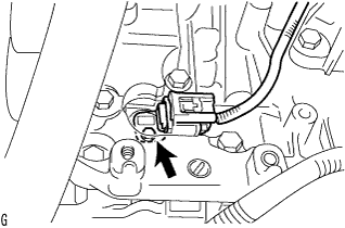 |
Install the sensor with the bolt.
- Torque:
- 10 N*m{102 kgf*cm, 7 ft.*lbf}
Connect the sensor connector.
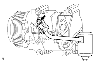
| 2. INSTALL COOLER COMPRESSOR ASSEMBLY |
Install the cooler compressor with the 4 bolts.
- Torque:
- 24.5 N*m{250 kgf*cm, 18 ft.*lbf}
- NOTICE:
- Tighten the bolts in the order shown in the illustration to install the cooler compressor.
 |
Connect the connector.
| 3. INSTALL NO. 1 COOLER REFRIGERANT DISCHARGE HOSE |
 |
Remove the attached vinyl tape from the hose.
Sufficiently apply compressor oil to a new O-ring and the fitting surface of the cooler compressor.
- Compressor oil:
- ND-OIL 8 or equivalent
Install the O-ring to the cooler refrigerant discharge hose.
Connect the cooler refrigerant discharge hose to the cooler compressor with the bolt.
- Torque:
- 9.8 N*m{100 kgf*cm, 7 ft.*lbf}
| 4. INSTALL NO. 1 COOLER REFRIGERANT SUCTION HOSE |
 |
Remove the attached vinyl tape from the hose.
Sufficiently apply compressor oil to a new O-ring and the fitting surface of the cooler compressor.
- Compressor oil:
- ND-OIL 8 or equivalent
Install the O-ring to the cooler refrigerant suction hose.
Connect the cooler refrigerant suction hose to the cooler compressor with the bolt.
- Torque:
- 9.8 N*m{100 kgf*cm, 7 ft.*lbf}
| 5. INSTALL V-RIBBED BELT |
Rotate the tensioner pulley counterclockwise, and then install the V-ribbed belt.
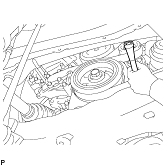 |
If it is difficult to install the V-ribbed belt, perform the following procedure.
Put the V-ribbed belt on everything except the tensioner pulley as shown in the illustration.
While releasing the belt tension by turning the belt tensioner counterclockwise, put the V-ribbed belt on the tensioner pulley.
- NOTICE:
- Put the backside of the V-ribbed belt on the tensioner pulley and idler pulley.
- Check that the V-ribbed belt is properly set to each pulley.
 |
| 6. INSTALL FRONT SUSPENSION MEMBER REINFORCEMENT RH |
Install the reinforcement with the 4 bolts.
- Torque:
- 96 N*m{978 kgf*cm, 71 ft.*lbf}
 |
| 7. INSTALL REAR ENGINE UNDER COVER RH |
Install the under cover with the 2 clips.
| 8. INSTALL NO. 1 ENGINE UNDER COVER |
Install the under cover with the 2 bolts, 4 screw and 12 clips.
| 9. CONNECT RADIATOR RESERVE TANK ASSEMBLY |
Connect the reservoir tank with the 2 bolts.
- Torque:
- 5.0 N*m{51 kgf*cm, 44 in.*lbf}
 |
| 10. INSTALL V-BANK COVER SUB-ASSEMBLY |
Attach the 3 clips to install the engine cover.
 |
| 11. CONNECT CABLE TO NEGATIVE BATTERY TERMINAL |
| 12. CHARGE REFRIGERANT |
Perform vacuum purging using a vacuum pump.
Charge refrigerant HFC-134a (R134a).
- Standard:
- 430 +-30 g (15.2 +-1.1 oz.)
- SST
- 09985-20010(09985-02130,09985-02150,09985-02090,09985-02110,09985-02010,09985-02050,09985-02060,09985-02070)
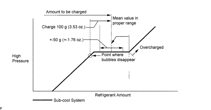
- NOTICE:
- Do not operate the cooler compressor before charging refrigerant as the cooler compressor will not work properly without any refrigerant, and will overheat.
- Approximately 100 g (3.53 oz.) of refrigerant may need to be charged after bubbles disappear. The refrigerant amount should be checked by measuring its quantity, and not with the sight glass.
| 13. INSPECT FOR REFRIGERANT LEAK |
After recharging the refrigerant gas, check for refrigerant gas leakage using a halogen leak detector.
Perform the operation under these conditions:
- Stop the engine.
- Secure good ventilation (the gas leak detector may react to volatile gases other than refrigerant, such as evaporated gasoline or exhaust gas).
- Repeat the test 2 or 3 times.
- Make sure that some refrigerant remains in the refrigeration system. When compressor is off: approximately 392 to 588 kPa (4 to 6 kgf/cm2, 57 to 85 psi)
- Stop the engine.
Using a gas leak detector, check the refrigerant line for leakage.
 |
If a gas leak is not detected on the drain hose, remove the blower motor control (blower resistor) from the cooling unit. Insert the gas leak detector sensor into the unit and perform the test.
Disconnect the connector and leave the pressure switch on for approximately 20 minutes. Bring the gas leak detector close to the pressure switch and perform the test.
| 14. INSTALL RADIATOR SUPPORT OPENING COVER |
Install the cover with the 9 clips.
 |