Lexus IS250 IS220d GSE20 ALE20 4GR-FSE ENGINE CONTROL SYSTEM
CAMSHAFT TIMING OIL CONTROL VALVE ASSEMBLY - INSTALLATION
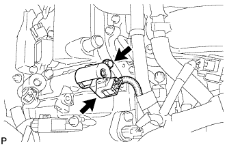
| 1. INSTALL CAMSHAFT TIMING OIL CONTROL VALVE (for Bank 2 Intake Side) |
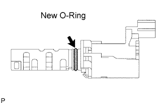
Apply a light coat of engine oil to a new O-ring and install it to the camshaft timing oil control valve.
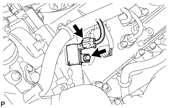
Install the camshaft timing oil control valve with the bolt.
- Torque:
- 10 N*m{ 102 kgf*cm, 7 ft.*lbf}
- NOTICE:
- Be careful that the O-ring is not cracked or jumped when installing the oil control valve.
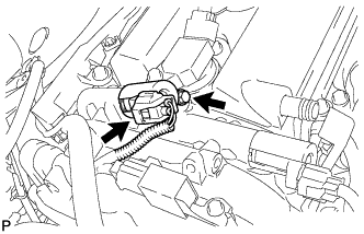
Connect the camshaft timing oil control valve connector.
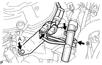
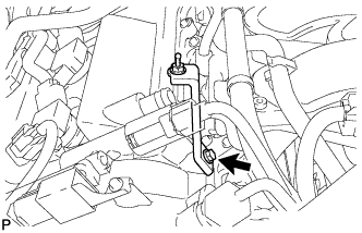
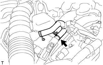
Install the bracket with the 2 bolts.
- Torque:
- Bolt A:
- 10 N*m{ 104 kgf*cm, 7 ft.*lbf}
- Bolt B:
- 21 N*m{ 214 kgf*cm, 16 ft.*lbf}
Connect the 2 wire harness clamps to the bracket.
| 2. INSTALL CAMSHAFT TIMING OIL CONTROL VALVE (for Bank 2 Exhaust Side) |
Apply a light coat of engine oil to a new O-ring and install it to the camshaft timing oil control valve.
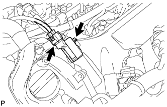
Install the camshaft timing oil control valve with the bolt.
- Torque:
- 10 N*m{ 102 kgf*cm, 7 ft.*lbf}
- NOTICE:
- Be careful that the O-ring is not cracked or jumped when installing the oil control valve.
Connect the camshaft timing oil control valve connector.
| 3. INSTALL CAMSHAFT TIMING OIL CONTROL VALVE (for Bank 1 Intake Side) |
Apply a light coat of engine oil to a new O-ring and install it to the camshaft timing oil control valve.
Install the camshaft timing oil control valve with the bolt.
- Torque:
- 10 N*m{ 102 kgf*cm, 7 ft.*lbf}
- NOTICE:
- Be careful that the O-ring is not cracked or jumped when installing the oil control valve.
Connect the camshaft timing oil control valve connector.
Install the V-bank cover bracket with the bolt.
- Torque:
- 10 N*m{ 102 kgf*cm, 7 ft.*lbf}
| 4. INSTALL CAMSHAFT TIMING OIL CONTROL VALVE (for Bank 1 Exhaust Side) |
Apply a light coat of engine oil to a new O-ring and install it to the camshaft timing oil control valve.
Install the camshaft timing oil control valve with the bolt.
- Torque:
- 10 N*m{ 102 kgf*cm, 7 ft.*lbf}
- NOTICE:
- Be careful that the O-ring is not cracked or jumped when installing the oil control valve.
Connect the camshaft timing oil control valve connector.
| 5. REMOVE INTAKE MANIFOLD |
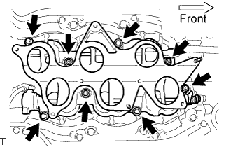
Install a new gasket and the intake manifold with the 4 bolts and 4 nuts.
- Torque:
- 21 N*m{ 214 kgf*cm, 15 ft.*lbf}
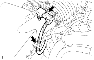
Connect the SCV position sensor connector.
Connect the DC motor connector for the SCV.
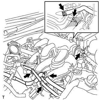
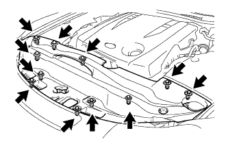
| 6. INSTALL INTAKE AIR SURGE TANK |
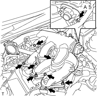
Install a new gasket to the intake air surge tank.
Using a 5 mm hexagon socket wrench, install the 6 bolts.
- Torque:
- Bolts except A:
- 18 N*m{ 184 kgf*cm, 13 ft.*lbf}
Install the bolt and 2 nuts to the intake air surge tank.
- Torque:
- Bolt A:
- 21 N*m{ 214 kgf*cm, 15 ft.*lbf}
- Nut:
- 16 N*m{ 163 kgf*cm, 12 ft.*lbf}
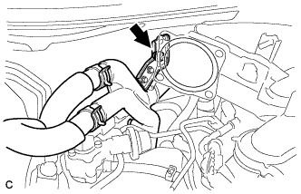
Install the surge tank stay to the intake air surge tank.
- Torque:
- 21 N*m{ 214 kgf*cm, 15 ft.*lbf}
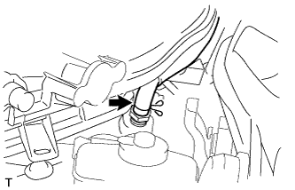
Connect the water hose joint with the bolt.
- Torque:
- 10 N*m{ 102 kgf*cm, 7 ft.*lbf}
Connect the ventilation hose to the intake air surge tank.
Connect the wire harness and hose to the intake air surge tank.
Connect the No. 1 vacuum switching valve assembly to the intake air surge tank.
- Torque:
- 18 N*m{ 184 kgf*cm, 13 ft.*lbf}
Connect the vacuum hose to the intake air surge tank.
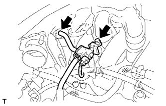
| 7. INSTALL THROTTLE BODY |
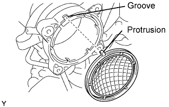
Install a new gasket to the intake air surge tank.
- HINT:
- Align the protrusion of the gasket on the intake air surge tank.
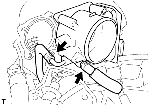
Connect the 2 water by-pass hoses to the throttle body.
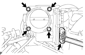
Install the throttle body with the 4 bolts.
- Torque:
- 10 N*m{ 102 kgf*cm, 7 ft.*lbf}
Connect the throttle motor connector.
| 8. INSTALL AIR CLEANER CAP WITH AIR CLEANER HOSE |
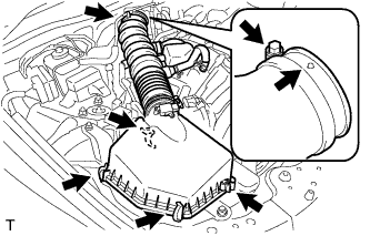
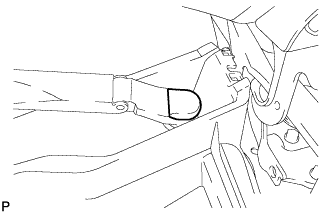
Install the air cleaner cap with air cleaner hose assembly with the 4 clamps and hose clamp.
- HINT:
- Be sure to install the air cleaner assembly so that the screw part of the hose clamp is as shown in the illustration.
Install the VSV hose to the air cleaner hose.
Connect the MAF meter connector and clamp to the air cleaner.
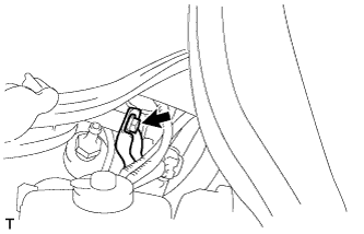
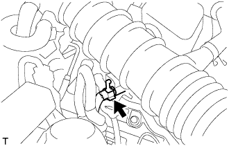
| 9. CONNECT NO. 2 VENTILATION HOSE |
Connect the ventilation hose to the cylinder head cover with the clamp.
| 10. ADD ENGINE COOLANT |
Tighten all the plugs and fill the radiator with TOYOTA Super Long Life Coolant (SLLC).
- Torque:
- 13 N*m{ 130 kgf*cm, 9 ft.*lbf}for cylinder block drain cock plug
Add engine coolant.
- Specified capacity:
- 9.1 liters (9.6 US qts, 8.0 lmp. qts)
- HINT:
Slowly pour coolant into the radiator reservoir until it reaches the FULL line.
Press the inlet and outlet radiator hoses several times by hand, and then check the level of the coolant.
If the coolant level is low, add coolant.
Install the radiator cap and reservoir cap.
Bleed air from the cooling system.
- NOTICE:
- Before starting the engine to warm up the engine, turn the A/C switch OFF.
Warm up the engine until the thermostat opens. While the thermostat is open, circulate the coolant for several minutes.
- HINT:
- The thermostat open timing can be confirmed by pressing the inlet radiator hose by hand, and checking when the engine coolant starts to flow inside the hose.
- NOTICE:
- When pressing the radiator hoses:
Maintain the engine speed at 2,000 to 2,500 rpm.
Press the inlet and outlet radiator hoses several times by hand to bleed air.
- NOTICE:
- When pressing the radiator hoses:
Stop the engine, and wait until the engine coolant cools down to ambient temperature.
- NOTICE:
- Do not remove the radiator cap while the engine and radiator are still hot. Pressurized, hot engine coolant and steam may be released and cause serious burns.
Check the coolant level in the radiator reservoir.
If the coolant level is low, add SLLC to the radiator reservoir FULL line.
| 11. CHECK FOR ENGINE COOLANT LEAKS |
- NOTICE:
- Before performing each inspection, turn the A/C switch OFF.
- CAUTION:
- Do not remove the radiator cap while the engine and radiator are still hot. Pressurized, hot engine coolant and steam may be released and cause serious burns.
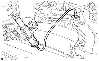
Fill the radiator with coolant and attach a radiator cap tester.
Warm up the engine.
Using a radiator cap tester, increase the pressure inside the radiator to 118 kPa (1.2 kgf*cm2, 17 psi), and check that the pressure does not drop.
If the pressure drops, check the hoses, radiator and water pump for leaks. If no external leaks are found, check the heater core, cylinder block and cylinder head.
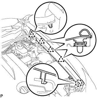
| 12. INSTALL COWL TOP VENTILATOR LOUVER SUB-ASSEMBLY |
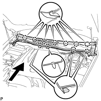
Engage the 11 claws.
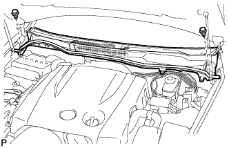
Install the cowl top ventilator louver sub-assembly with the 2 clips.
| 13. INSTALL WINDSHIELD WIPER ARM AND BLADE ASSEMBLY LH |
Operate the wiper, and stop the windshield wiper motor at the automatic stop position.
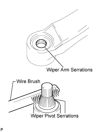
Clean the wiper arm serrations.
Clean the wiper pivot serrations with a wire brush (when reinstalling).
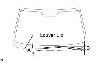
Install the front wiper arm and blade assembly LH with the nut at the position as shown in the illustration.
- Torque:
- 22 N*m{ 224 kgf*cm, 16 ft.*lbf}
- HINT:
- Hold the arm hinge by hand to fasten the nut.
| Area | Measurement |
| A | 15 to 30 mm (0.59 to 1.18 in.) |
| B | Approx. 40 mm (1.57 in.) |
| 14. INSTALL WINDSHIELD WIPER ARM AND BLADE ASSEMBLY RH |
Operate the wiper, and stop the windshield wiper motor at the automatic stop position.
Clean the wiper arm serrations.
Clean the wiper pivot serrations with a wire brush (when reinstalling).
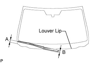
Install the front wiper arm and blade assembly RH with the nut at the position as shown in the illustration.
- Torque:
- 22 N*m{ 224 kgf*cm, 16 ft.*lbf}
- HINT:
- Hold the arm hinge by hand to fasten the nut.
| Area | Measurement |
| A | 18.5 to 33.5 mm (0.73 to 1.32 in.) |
| B | Approx. 20 mm (0.79 in.) |
Operate the front wipers while spraying washer fluid on the windshield glass. Make sure that the front wipers function properly and there is no interference with the vehicle body.
| 15. INSTALL FRONT WIPER ARM HEAD CAP |
Install the front wiper arm head cap.
- HINT:
- Use the same procedures for the RH side and the LH side.
| 16. INSTALL ROOF DRIP SIDE FINISH MOULDING LH |
| 17. INSTALL ROOF DRIP SIDE FINISH MOULDING RH |
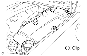
| 18. INSTALL FRONT FENDER PROTECTOR UPPER LH |
Engage the claw and the 3 clips, then install the front upper fender protector LH.
Engage the clip on the rubber portion of the cowl top ventilator louver sub-assembly to the front fender protector upper LH.
| 19. INSTALL FRONT FENDER PROTECTOR UPPER RH |
- HINT:
- Installation procedure of the RH side is the same as that of the LH side.
| 20. INSTALL V-BANK COVER SUB-ASSEMBLY |
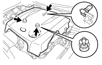
Engage the 2 clips on the front of the cover, and then engage the clip on the rear to install the V-bank cover.
- NOTICE:
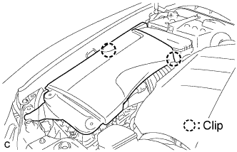
| 21. INSTALL ENGINE ROOM SIDE COVER LH |
Install the side cover with the 5 clips.
| 22. INSTALL ENGINE ROOM SIDE COVER RH |
Install the side cover with the 2 clips.
| 23. INSTALL COOL AIR INTAKE DUCT SEAL |
Install the intake duct seal with the 11 clips.