Lexus IS250 IS220d GSE20 ALE20 4GR-FSE ENGINE CONTROL SYSTEM
CHECK ANY OTHER DTC OUTPUT (IN ADDITION TO MISFIRE DTCS)
READ VALUE OF INTELLIGENT TESTER (MISFIRE RPM AND MISFIRE LOAD)
CHECK PCV HOSE (HOSE CONNECTION)
CHECK MISFIRE COUNT (CYL #1, #2, #3, #4, #5 AND #6)
CHECK CYLINDER COMPRESSION PRESSURE (MISFIRING CYLINDER)
CHANGE NORMAL SPARK PLUG AND CHECK SPARK OF MISFIRING CYLINDER
CHECK FUEL PRESSURE (LOW PRESSURE SIDE)
CHECK FUEL PRESSURE (HIGH PRESSURE SIDE)
READ VALUE OF INTELLIGENT TESTER (COOLANT TEMP)
READ VALUE OF INTELLIGENT TESTER (MAF)
DTC P0300 Random / Multiple Cylinder Misfire Detected
DTC P0301 Cylinder 1 Misfire Detected
DTC P0302 Cylinder 2 Misfire Detected
DTC P0303 Cylinder 3 Misfire Detected
DTC P0304 Cylinder 4 Misfire Detected
DTC P0305 Cylinder 5 Misfire Detected
DTC P0306 Cylinder 6 Misfire Detected
DESCRIPTION
When the engine misfires, high concentrations of hydrocarbons (HC) enter the exhaust gas. Extremely high HC concentration levels can cause increase in exhaust emission levels. High concentrations of HC can also cause increases in the Three-Way Catalytic Converter (TWC) temperature, which may cause damage to the TWC. To prevent this increase in emissions and to limit the possibility of thermal damage, the ECM monitors the misfire rate. When the temperature of the TWC reaches the point of thermal degradation, the ECM blinks the MIL. To monitor misfires, the ECM uses both the Camshaft Position (CMP) sensor and the Crankshaft Position (CKP) sensor. The CMP sensor is used to identify any misfiring cylinders and the CKP sensor is used to measure variations in the crankshaft rotation speed. Misfires are counted when the crankshaft rotation speed variations exceed predetermined thresholds.
If the misfire exceeds the threshold levels, and could cause emission deterioration, the ECM illuminates the MIL and set a DTC.
| DTC No. | DTC Detection Condition | Trouble Area |
| P0300 | Simultaneous misfiring of several cylinder detected (2 trip detection logic) | Open or short in engine wire harness Connector connection Vacuum hose connections Ignition system Injector Fuel pressure Mass Air Flow (MAF) meter Engine Coolant Temperature (ECT) sensor Compression pressure Valve clearance Valve timing PCV valve and hose PCV hose connections Air induction system ECM |
| P0301 P0302 P0303 P0304 P0305 P0306 | Misfiring of specific cylinder detected (2 trip detection logic) | Open or short in engine wire harness Connector connection Vacuum hose connections Ignition system Injector Fuel pressure Mass Air Flow (MAF) meter Engine Coolant Temperature (ECT) sensor Compression pressure Valve clearance Valve timing PCV valve and hose PCV hose connections Air induction system ECM |
When DTCs for misfiring cylinders are randomly set, but DTC P0300 is not set, it indicates that misfires have been detected in different cylinders at different times. DTC P0300 is only set when several misfiring cylinders are detected at the same time.
- HINT:
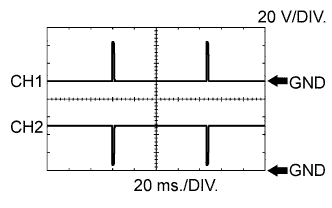
| Item | Content |
| Terminals | CH 1: #10 to #60 - E1 CH 2: INJF - E1 |
| Equipment Settings | 20 V/DIV. 20 ms./DIV. |
| Conditions | Idling |
WIRING DIAGRAM
Refer to DTC P0200 .
Refer to DTC P0351 .
CONFIRMATION DRIVING PATTERN
- HINT:
- In order to store misfire DTCs, it is necessary to drive the vehicle for the period of time shown in the table below, with the Misfire RPM and Misfire Load in the Data List.
| Engine RPM | Duration |
| Idling | 3.5 minutes or more |
| 1,000 | 3 minutes or more |
| 2,000 | 1.5 minutes or more |
| 3,000 | 1 minute or more |
- HINT:
- Do not turn the engine switch off until the stored DTC(s) and freeze data have been recorded. When the ECM returns to normal mode (default), the stored DTC(s), freeze frame data and other data will be erased.
INSPECTION PROCEDURE
- HINT:
In the event of DTC P0300 being present, perform the following operations:
| 1.CHECK ANY OTHER DTC OUTPUT (IN ADDITION TO MISFIRE DTCS) |
Connect the intelligent tester to the DLC3.
Turn the engine switch on (IG).
Turn the tester ON.
Enter the following menus: Power train / Engine / DTC.
Read DTCs.
- Result:
Display (DTC output) Proceed to P0300, P0301, P0302, P0303, P0304, P0305 and/or P0306 A P0300, P0301, P0302, P0303, P0304, P0305 and/or P0306 and other DTCs B
- HINT:
- If any DTCs other than P0300, P0301, P0302, P0303, P0304, P0305 and P0306 are output, troubleshoot those DTCs first.
|
| ||||
| A | |
| 5.CHECK SPARK PLUG |
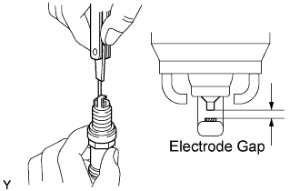
Remove the ignition coil and the spark plug of the misfiring cylinder.
Measure the spark plug electrode gap.
- Standard:
- Between 1.0 mm and 1.1 mm (0.039 in. and 0.043 in.)
Check the electrode for carbon deposits.
| Manufacture | Product |
| DENSO | FK20HBR11 |
| NGK | ILFR6D11T |
- NOTICE:
- If the electrode gap is larger than standard, replace the spark plug. Do not adjust the electrode gap.
|
| ||||
| OK | |
| 7.CHECK CYLINDER COMPRESSION PRESSURE (MISFIRING CYLINDER) |
Measure the cylinder compression pressure of the misfiring cylinder.
|
| ||||
| NG | ||
| ||
| 8.CHANGE NORMAL SPARK PLUG AND CHECK SPARK OF MISFIRING CYLINDER |
Change the installed spark plug to a spark plug that functions normally.
Perform a spark test.
- CAUTION:
- Always disconnect each injector connector.
- NOTICE:
- Do not crank the engine for more than 2 seconds.
Install the spark plug to the ignition coil and connect the ignition coil connector.
Disconnect the injector connector.
Ground the spark plug.
Check if sparks occur while the engine is being cranked.
- OK:
- Sparks jump across electrode gap.
|
| ||||
| OK | ||
| ||
| 9.CHECK AIR INDUCTION SYSTEM |
Check the air induction system for vacuum leakage.
- OK:
- No leakage from air induction system.
|
| ||||
| OK | |
| 10.CHECK VALVE TIMING |
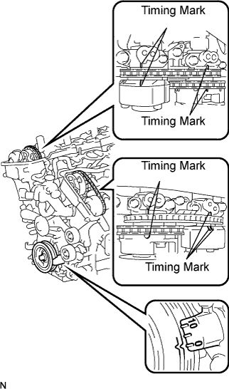
Remove the cylinder head covers.
Turn the crankshaft pulley, and align its groove with the timing mark "0" of the timing chain cover.
Check that the timing marks of the camshaft timing gears aligned with the timing marks of the bearing cap as shown in the illustration.
If not, turn the crankshaft 1 revolution (360°) and align the marks as above.
- OK:
- Timing marks on camshaft timing gears are aligned as shown in illustration.
Reinstall the cylinder head covers.
|
| ||||
| OK | |
| 11.CHECK FUEL PRESSURE (LOW PRESSURE SIDE) |
Check the fuel pressure (low pressure side) .
|
| ||||
| OK | |
| 12.CHECK FUEL PRESSURE (HIGH PRESSURE SIDE) |
Check the fuel pressure (high pressure side) .
|
| ||||
| OK | |
| 13.READ VALUE OF INTELLIGENT TESTER (COOLANT TEMP) |
Connect the intelligent tester to the DLC3.
Turn the engine switch on (IG).
Turn the tester ON.
Enter the following menus: Power train / Engine / Data List / Coolant Temp.
Read the COOLANT TEMP twice, when the engine is both cold and warmed up.
- Standard:
- With cold engine:
- Same as ambient air temperature.
- With warm engine:
- Between 75°C and 95°C (167°F and 203°F).
|
| ||||
| OK | |
| 14.READ VALUE OF INTELLIGENT TESTER (MAF) |
Connect the intelligent tester to the DLC3.
Turn the engine switch on (IG).
Turn the tester ON.
Enter the following menus: Power train / Engine / Data List / MAF and Coolant Temp.
Allow the engine to idle until the COOLANT TEMP reaches 75°C (167°F) or more.
Read the MAF with the engine in an idling condition and at an engine speed of 2,500 rpm.
- Standard:
- MAF while engine idling:
- Between 2.1 g/s and 3.1 g/s (shift position: N, A/C: OFF).
- MAF at engine speed of 2,500 rpm:
- Between 7.8 g/s and 11.4 g/s (shift position: N, A/C: OFF).
|
| ||||
| OK | ||
| ||