Lexus IS250 IS220d GSE20 ALE20 4GR-FSE ENGINE CONTROL SYSTEM
CHECK HARNESS AND CONNECTOR (ECM - ETCS FUSE, ETCS FUSE - BATTERY)
DTC P2118 Throttle Actuator Control Motor Current Range / Performance
DESCRIPTION
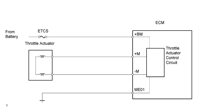
The ETCS (Electronic Throttle Control System) has a dedicated power supply circuit. The voltage (+BM) is monitored and when it is low (less than 4 V), the ECM determines that there is a malfunction in the ETCS and cuts off the current to the throttle actuator.
When the voltage becomes unstable, the ETCS itself becomes unstable. For this reason, when the voltage is low, the current to the throttle actuator is cut. If repairs are made and the system returns to normal, turn the engine switch to off. The ECM then allows the current to flow to the throttle actuator so that it can be restarted.
- HINT:
- The ETCS does not use a throttle cable.
| DTC No. | DTC Detection Condition | Trouble Area |
| P2118 | Open in ETCS power source (+BM) circuit (1 trip detection logic) | Open in ETCS power source circuit ETCS fuse ECM |
FAIL-SAFE
When this DTC, as well as other DTCs relating to ETCS (Electronic Throttle Control System) malfunctions, is set, the ECM enters fail-safe mode. During fail-safe mode, the ECM cuts the current to the throttle actuator off, and the throttle valve is returned to a 6° throttle angle by the return spring. The ECM then adjusts the engine output by controlling the fuel injection (intermittent fuel-cut) and ignition timing, in accordance with the accelerator pedal opening angle, to allow the vehicle to continue at a minimal speed. If the accelerator pedal is depressed firmly and gently, the vehicle can be driven slowly.
Fail-safe mode continues until a pass condition is detected, and the engine switch is then turned to off.
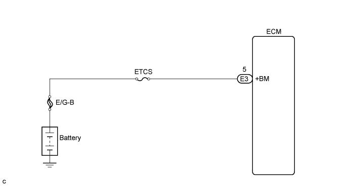
WIRING DIAGRAM
INSPECTION PROCEDURE
- HINT:
- Read freeze frame data using the intelligent tester. Freeze frame data records the engine conditions when malfunctions are detected. When troubleshooting, freeze frame data can help determine if the vehicle was moving or stationary, if the engine was warmed up or not, if the air-fuel ratio was lean or rich, and other data from the time the malfunction occurred .
| 1.CHECK FUSE (ETCS FUSE) |
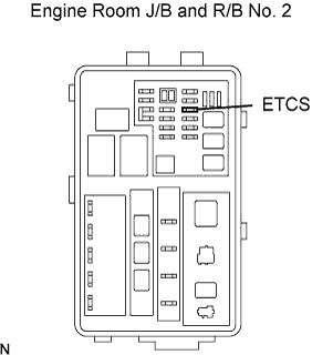
Remove the ETCS fuse from the engine room J/B and R/B No. 2.
Measure the resistance of the ETCS fuse.
- Standard resistance:
- Below 1 Ω
Reinstall the ETCS fuse.
|
| ||||
| OK | |
| 2.INSPECT ECM (+BM VOLTAGE) |
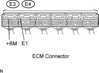
Measure the voltage of the E3 and E4 ECM connectors.
- Standard voltage:
Tester Connection Specified Condition +BM (E3-5) - E1 (E4-7) 9 to 14 V
|
| ||||
| NG | |
| 3.CHECK HARNESS AND CONNECTOR (ECM - ETCS FUSE, ETCS FUSE - BATTERY) |
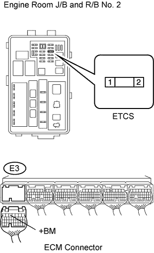
Check the harness and connector between the ETCS fuse and ECM.
Remove the ETCS fuse from the engine room J/B and R/B No. 2.
Disconnect the E3 ECM connector.
Measure the resistance of the wire harness side connector.
- Standard resistance (Check for open):
Tester Connection Specified Condition ETCS fuse (2) - +BM (E3-5) Below 1 Ω
- Standard resistance (Check for short):
Tester Connection Specified Condition ETCS fuse (2) or +BM (E3-5) - Body ground 10 kΩ or higher
Reinstall the ETCS fuse.
Reconnect the ECM connector.
Check the harness and connector between the ETCS fuse and positive battery cable.
Remove the ETCS fuse from the engine room J/B and R/B No. 2.
Disconnect the positive battery cable.
Measure the resistance of the wire harness side connector.
- Standard resistance (Check for open):
Tester Connection Specified Condition Positive battery cable - ETCS fuse (1) Below 1 Ω
- Standard resistance (Check for short):
Tester Connection Specified Condition Positive battery cable or ETCS fuse (1) - Body ground 10 kΩ or higher
Reinstall the ETCS fuse.
Reconnect the positive battery cable.
|
| ||||
| OK | ||
| ||