Upper Instrument Panel -- Removal |
| 1. TABLE OF BOLT, SCREW AND NUT |
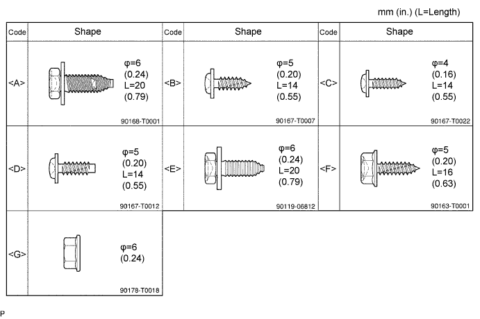
- HINT:
- All bolts, screws and nuts relevant to installing and removing the instrument panel are shown along with an alphabetical code in the table below.
| 2. DISCONNECT CABLE FROM NEGATIVE BATTERY TERMINAL |
- CAUTION:
- Wait at least 90 seconds after disconnecting the cable from the negative (-) battery terminal to prevent airbag and seat belt pretensioner activation.
| 3. PLACE FRONT WHEELS FACING STRAIGHT AHEAD |
| 4. REMOVE STEERING PAD ASSEMBLY |
 |
Straighten the front wheels.
Using a T30 "torx" socket, loosen the 2 screws until the groove along each screw circumference catches on the screw case.
Pull out the steering pad from the steering wheel and support the steering pad with one hand as shown in the illustration.
- NOTICE:
- When removing the steering pad, do not pull the airbag wire harness.
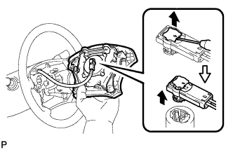 |
Using a screwdriver, disconnect the airbag connector.
- NOTICE:
- When handling the airbag connector, do not damage the airbag wire harness.
Disconnect the horn connector and remove the steering pad.
| 5. REMOVE STEERING WHEEL ASSEMBLY |
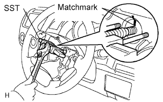
Remove the steering wheel set nut.
Place matchmarks on the steering wheel and main shaft.
Using SST, remove the steering wheel.
- SST
- 09950-50013(09951-05010,09952-05010,09953-05020,09954-05021)
 |
| 6. REMOVE STEERING COLUMN COVER LOWER |
Remove the 3 screws and lower cover.
 |
| 7. REMOVE STEERING COLUMN COVER UPPER |
Remove the 3 screws and lower cover.
|
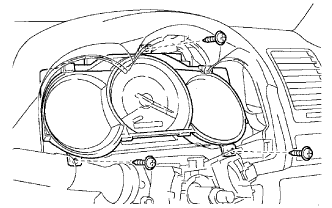
| 8. REMOVE INSTRUMENT CLUSTER FINISH PANEL NO.1 |
 |
Remove the clip.
Detach the 2 claws and remove the panel.
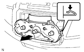
| 9. REMOVE COMBINATION METER ASSEMBLY |
 |
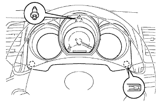
- NOTICE:
- There are 2 types of combination meters. One type has a 40 pin connector and 16 pin connector. The other type only has a 40 pin connector.
Remove the 3 screws.
Disconnect all connectors and remove the combination meter.
| 10. REMOVE HEATER CONTROL KNOB |
 |
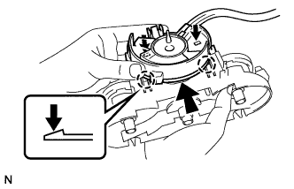
Remove the 3 control knobs.
| 11. REMOVE FRE/REC CONTROL KNOB |
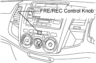 |
Remove the control knob.
| 12. REMOVE INSTRUMENT CLUSTER FINISH PANEL ASSEMBLY CENTER |
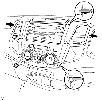 |
- HINT:
- To prevent the clips from falling, horizontally pull out the panel. Hold both sides of the panel in the locations indicated by the arrows in the illustration.
Remove the screw <C>.
Detach the 6 claws and 4 clips.
- NOTICE:
- Make sure the center registers are not removed.
Disconnect all connectors and remove the panel.
| 13. REMOVE AIR CONDITIONING CONTROL ASSEMBLY |
Detach the 2 claws and disconnect the A/C control.
 |
Detach the 2 claws and disconnect the air inlet damper control cable.
 |
Disconnect the connector.
Detach the 2 claws and disconnect the heater control cable.
 |
Detach the 2 claws and disconnect the air mix damper control cable.
Remove the A/C control.
| 14. REMOVE RADIO RECEIVER ASSEMBLY WITH BRACKET |
Remove the 4 screws.
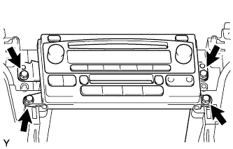 |
Disconnect all connectors and remove the radio receiver with bracket.
w/o Stereo opening cover:
Remove the 4 screws and No. 1 radio bracket from the radio receiver.
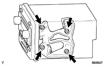 |
w/o Stereo opening cover:
Remove the 4 screws and No. 2 radio bracket from the radio receiver.
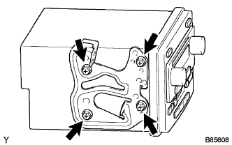 |
| 15. REMOVE GLOVE COMPARTMENT DOOR ASSEMBLY |
 |
Open the glove compartment door.
While pushing in the sides of the glove compartment door as indicated by the arrows in the illustration, open the door to release it from the 2 stoppers.
Open the door until it is horizontal.
Pull the glove compartment door toward the rear of the vehicle to detach the 2 hinges and remove the glove compartment door.
 |
| 16. REMOVE FRONT PASSENGER AIRBAG ASSEMBLY |
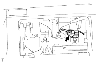 |
Disconnect the connector from the airbag.
- NOTICE:
- When handling the airbag connector, do not damage the airbag wire harness.
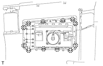
Remove the 2 bolts.
 |
Detach the clamp from the bracket.
Detach the 12 claws and remove the airbag.
 |
| 17. REMOVE FRONT PILLAR GARNISH LH |
Using a clip remover, detach the 2 clips.
 |
Pull the garnish in the direction indicated by the arrow in the illustration to detach the 2 claws. Then remove the garnish.
| 18. REMOVE FRONT PILLAR GARNISH RH |
- HINT:
- Use the same procedures described for the LH side.
| 19. REMOVE UPPER INSTRUMENT PANEL SUB-ASSEMBLY |

- NOTICE:
- Be careful not to damage the steering wheel.
Remove the 2 bolts <A> and 2 screws <B>.
Pull up the instrument panel to detach the 8 claws.
Disconnect all connectors.
Remove the instrument panel.