Audio And Visual System Illumination Circuit
DESCRIPTION
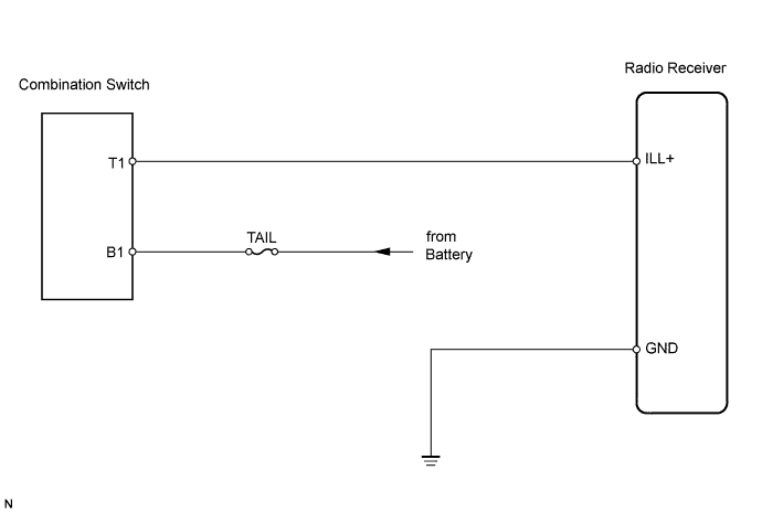
WIRING DIAGRAM
INSPECTION PROCEDURE
CHECK WIRE HARNESS (RADIO RECEIVER - BATTERY AND BODY GROUND)
AUDIO AND VISUAL SYSTEM - Illumination Circuit |
DESCRIPTION
The radio receiver panel illuminates when the light control switch is in the TAIL or HEAD position.
WIRING DIAGRAM
INSPECTION PROCEDURE
| 1.CHECK WIRE HARNESS (RADIO RECEIVER - BATTERY AND BODY GROUND) |
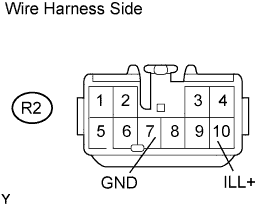
Disconnect the R2 receiver connector.
Measure the voltage and resistance of the wire harness side connector.
- Standard resistance:
Tester Connection
| Specified Condition
|
R2-7 (GND) - Body ground
| Below 1 Ω
|
- Standard voltage:
Tester Connection
| Condition
| Specified Condition
|
R2-10 (ILL+) - Body ground
| Light control switch OFF
| Below 1 V
|
R2-10 (ILL+) - Body ground
| Light control switch TAIL or HEAD
| 10 to 14 V
|
| | REPAIR OR REPLACE HARNESS AND CONNECTOR |
|
|
| OK |
|
|
|
| REPLACE RADIO RECEIVER ASSEMBLY |
|