Meter / Gauge System Warning Buzzer Does Not Sound
WIRING DIAGRAM
INSPECTION PROCEDURE
INSPECT FUSE (TAIL)
INSPECT HEADLIGHT DIMMER SWITCH ASSEMBLY (LIGHT CONTROL SWITCH)
CHECK WIRE HARNESS (HEADLIGHT DIMMER SWITCH - METER AND BATTERY)
INSPECT FRONT DOOR COURTESY LIGHT SWITCH ASSEMBLY (for Driver Side)
CHECK WIRE HARNESS (FRONT DOOR COURTESY LIGHT SWITCH - METER)
METER / GAUGE SYSTEM - Warning Buzzer does not Sound |
WIRING DIAGRAM
INSPECTION PROCEDURE
Remove the TAIL fuse from the driver side junction block.
Measure the resistance of the fuse.
- Standard resistance:
- Below 1 Ω
| 2.INSPECT HEADLIGHT DIMMER SWITCH ASSEMBLY (LIGHT CONTROL SWITCH) |
Remove the headlight dimmer switch.
Measure the resistance of the switch.
- Standard resistance:
for LHDTester Connection
| Switch Condition
| Specified Condition
|
13 (B1) - 10 (T1)
| HEAD
| Below 1 Ω
|
13 (B1) - 10 (T1)
| TAIL
| Below 1 Ω
|
13 (B1) - 10 (T1)
| OFF
| 10 kΩ or higher
|
- for RHD:
Tester Connection
| Switch Condition
| Specified Condition
|
5 (B1) - 8 (T1)
| HEAD
| Below 1 Ω
|
5 (B1) - 8 (T1)
| TAIL
| Below 1 Ω
|
5 (B1) - 8 (T1)
| OFF
| 10 kΩ or higher
|
| | REPLACE HEADLIGHT DIMMER SWITCH ASSEMBLY |
|
|
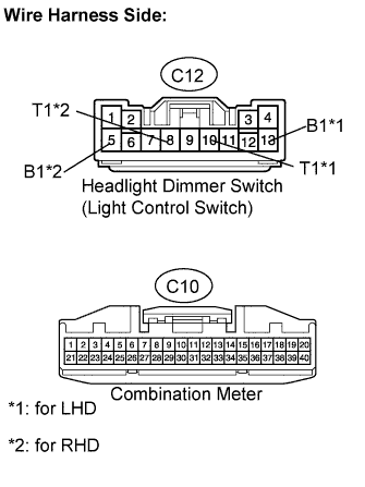
| 3.CHECK WIRE HARNESS (HEADLIGHT DIMMER SWITCH - METER AND BATTERY) |
Disconnect the C12 switch connector.
Disconnect the C10 meter connector.
Measure the voltage of the wire harness side connector.
- Standard voltage:
for LHDTester Connection
| Specified Condition
|
C12-13 (B1) - Body ground
| 10 to 14 V
|
- for RHD:
Tester Connection
| Specified Condition
|
C12-5 (B1) - Body ground
| 10 to 14 V
|
Measure the resistance of the wire harness side connectors.
- Standard resistance:
for LHDTester Connection
| Specified Condition
|
C12-10 (T1) - C10-8
| Below 1 Ω
|
C12-10 (T1) - Body ground
| 10 kΩ or higher
|
- for RHD:
Tester Connection
| Specified Condition
|
C12-8 (T1) - C10-8
| Below 1 Ω
|
C12-8 (T1) - Body ground
| 10 kΩ or higher
|
| | REPAIR OR REPLACE HARNESS OR CONNECTOR |
|
|
| 4.INSPECT FRONT DOOR COURTESY LIGHT SWITCH ASSEMBLY (for Driver Side) |
Remove the courtesy light switch.
Measure the resistance of the switch.
- Standard resistance:
Tester Connection
| Switch Condition
| Specified Condition
|
1 - Body ground
| Not pushed (OFF)
| Below 1 Ω
|
1 - Body ground
| Pushed (ON)
| 10 kΩ or higher
|
| | REPLACE FRONT DOOR COURTESY LIGHT SWITCH ASSEMBLY (for Driver Side) |
|
|
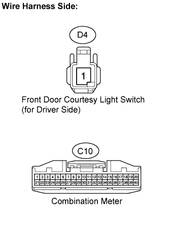
| 5.CHECK WIRE HARNESS (FRONT DOOR COURTESY LIGHT SWITCH - METER) |
Disconnect the D4 switch connector.
Disconnect the C10 meter connector.
Measure the resistance of the wire harness side connectors.
- Standard resistance:
Tester Connection
| Specified Condition
|
D4-1 - C10-16
| Below 1 Ω
|
D4-1 - Body ground
| 10 kΩ or higher
|
| | REPAIR OR REPLACE HARNESS OR CONNECTOR |
|
|
| OK |
|
|
|
| REPLACE COMBINATION METER ASSEMBLY |
|