Meter / Gauge System Speedometer Malfunction
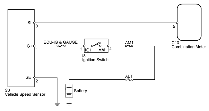
WIRING DIAGRAM
INSPECTION PROCEDURE
INSPECT FUSE (ECU-IG & GAUGE)
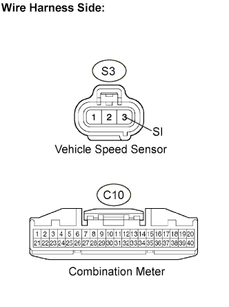
CHECK VEHICLE SPEED SENSOR
CHECK COMBINATION METER ASSEMBLY
CHECK WIRE HARNESS (SENSOR - BATTERY AND BODY GROUND)
CHECK WIRE HARNESS (SENSOR - METER)
METER / GAUGE SYSTEM - Speedometer Malfunction |
WIRING DIAGRAM
INSPECTION PROCEDURE
| 1.INSPECT FUSE (ECU-IG & GAUGE) |
Remove the ECU-IG & GAUGE fuse from the driver side junction block.
Measure the resistance of the fuse.
- Standard resistance:
- Below 1 Ω
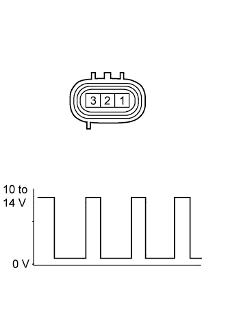
| 2.CHECK VEHICLE SPEED SENSOR |
Measure the voltage of the sensor.
- Standard voltage:
Tester Connection
| Condition
| Specified Condition
|
2 - 3
| - Ignition switch ON
- Shift lever on N
- Slowly rotate rear wheel
| 10 to 14 V
(Pulse generation)
|
- HINT:
- Connect the tester's positive (+) lead to terminal 3, and negative (-) lead to terminal 2.
| | REPLACE VEHICLE SPEED SENSOR |
|
|
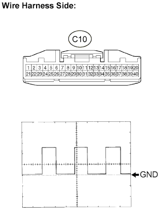
| 3.CHECK COMBINATION METER ASSEMBLY |
Disconnect the C10 meter connector.
Using an oscilloscope, check the signal waveform of the meter.
Tester Connection
| Tool Setting
| Vehicle Condition
|
C10-5 - Body ground
| 5 V/DIV., 20 msec./DIV.
| Drive vehicle at 20 km/h (12 mph)
|
- OK:
- Refer to the illustration.
- HINT:
- As the vehicle speed increases, the wavelength shortens.
| | REPLACE COMBINATION METER ASSEMBLY |
|
|
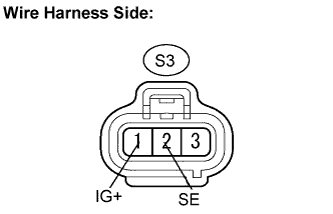
| 4.CHECK WIRE HARNESS (SENSOR - BATTERY AND BODY GROUND) |
Disconnect the S3 sensor connector.
Measure the voltage of the wire harness side connector.
- Standard voltage:
Tester Connection
| Condition
| Specified Condition
|
S3-1 (IG+) - Body ground
| Ignition switch ON
| 10 to 14 V
|
S3-1 (IG+) - Body ground
| Ignition switch OFF
| Below 1 V
|
Measure the resistance of the wire harness side connector.
- Standard resistance:
Tester Connection
| Specified Condition
|
S3-2 (SE) - Body ground
| Below 1 Ω
|
| | REPAIR OR REPLACE HARNESS OR CONNECTOR |
|
|
| 5.CHECK WIRE HARNESS (SENSOR - METER) |
Disconnect the S3 sensor connector.
Disconnect the C10 meter connector.
Measure the resistance of the wire harness side connectors.
- Standard resistance:
Tester Connection
| Specified Condition
|
S3-3 (SI) - C10-5
| Below 1 Ω
|
S3-3 (SI) - Body ground
| 10 kΩ or higher
|
| | REPAIR OR REPLACE HARNESS OR CONNECTOR |
|
|
| OK |
|
|
|
| REPLACE COMBINATION METER ASSEMBLY |
|