Meter / Gauge System Entire Combination Meter Does Not Operate
WIRING DIAGRAM
INSPECTION PROCEDURE
INSPECT FUSE (DCC, DOME, MET)
CHECK WIRE HARNESS (METER - BATTERY AND BODY GROUND)
METER / GAUGE SYSTEM - Entire Combination Meter does not Operate |
WIRING DIAGRAM
INSPECTION PROCEDURE
| 1.INSPECT FUSE (DCC, DOME, MET) |
Remove the DCC and DOME fuses from the engine room junction block.
Remove the MET fuse from the driver side junction block.
Measure the resistance of the fuses.
- Standard resistance:
- Below 1 Ω
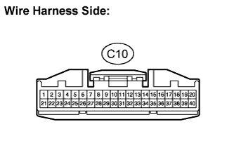
| 2.CHECK WIRE HARNESS (METER - BATTERY AND BODY GROUND) |
Disconnect the C10 meter connector.
Measure the voltage of the wire harness side connector.
- Standard voltage:
Tester Connection
| Condition
| Specified Condition
|
C10-1 - Body ground
| Always
| 10 to 14 V
|
C10-21 - Body ground
| Ignition switch ON
| 10 to 14 V
|
C10-21 - Body ground
| Ignition switch OFF
| Below 1 V
|
Measure the resistance of the wire harness side connector.
- Standard resistance:
Tester Connection
| Specified Condition
|
C10-22 - Body ground
| Below 1 Ω
|
| | REPAIR OR REPLACE HARNESS OR CONNECTOR |
|
|
| OK |
|
|
|
| REPLACE COMBINATION METER ASSEMBLY |
|