Wireless Door Lock Control System (For Non-Built-In Type Door Control Receiver) No Answer-Back
DESCRIPTION
WIRING DIAGRAM
INSPECTION PROCEDURE
CHECK WIRELESS DOOR LOCK CONTROL FUNCTION
CHECK HAZARD WARNING LIGHT
CHECK WIRE HARNESS (INTEGRATION RELAY - TURN SIGNAL FLASHER RELAY)
WIRELESS DOOR LOCK CONTROL SYSTEM (for Non-built-in Type Door Control Receiver) - No Answer-Back |
DESCRIPTION
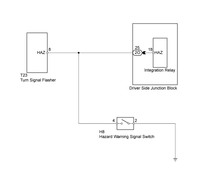
In this case, wireless control functions are normal but the hazard warning light answer-back is not normal (the instrument panel junction block's (integration relay) turn signal flasher relay output may be malfunctioning).
WIRING DIAGRAM
INSPECTION PROCEDURE
| 1.CHECK WIRELESS DOOR LOCK CONTROL FUNCTION |
Check the wireless door lock functions by operating the transmitter switches.
ResultResult
| Proceed to
|
Wireless door lock functions are normal but hazard warning lights' answer-back does not occur
| A
|
Wireless door lock functions are abnormal
| B
|
| | GO TO FLOWCHART (ONLY WIRELESS CONTROL FUNCTION IS INOPERATIVE) |
|
|
| 2.CHECK HAZARD WARNING LIGHT |
Check that the hazard warning lights flash when the hazard warning signal switch is pressed.
- OK:
- Hazard warning lights flash when hazard warning signal switch is pressed.
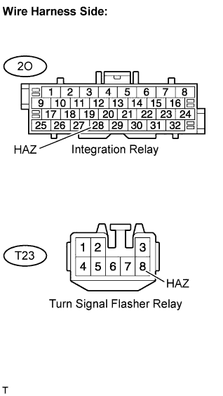
| 3.CHECK WIRE HARNESS (INTEGRATION RELAY - TURN SIGNAL FLASHER RELAY) |
Disconnect the 2O junction block connector.
Disconnect the T23 relay connector.
Measure the resistance of the wire harness side connectors.
- Standard resistance:
Tester Connection
| Specified Condition
|
2O-28 (HAZ) - T23-8 (HAZ)
| Below 1 Ω
|
| | REPAIR OR REPLACE HARNESS OR CONNECTOR |
|
|
| OK |
|
|
|
| REPLACE DRIVER SIDE JUNCTION BLOCK ASSEMBLY |
|