Lighting System Headlight Leveling Ecu Power Source Circuit
DESCRIPTION
WIRING DIAGRAM
INSPECTION PROCEDURE
READ VALUE USING INTELLIGENT TESTER (IGNITION POWER SUPPLY)
CHECK HARNESS AND CONNECTOR (HEADLIGHT LEVELING ECU ASSEMBLY - BATTERY AND BODY GROUND)
LIGHTING SYSTEM - Headlight Leveling ECU Power Source Circuit |
DESCRIPTION
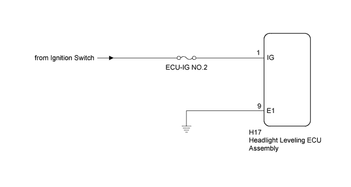
This circuit detects the state of the ignition switch, and sends it to the headlight leveling ECU.
WIRING DIAGRAM
INSPECTION PROCEDURE
- NOTICE:
- Inspect the fuses for circuits related to this system before performing the following inspection procedure.
- HINT:
- After replacing the headlight leveling ECU, initialization of the ECU is necessary (Toyota Fortuner RM000002CE402CX.html).
| 1.READ VALUE USING INTELLIGENT TESTER (IGNITION POWER SUPPLY) |
Using the intelligent tester, read the Data List (Toyota Fortuner RM000000PKV08JX.html).
HL Auto LevelingTester Display
| Measurement Item/Range
| Normal Condition
| Diagnostic Note
|
+B
| Ignition power supply voltage value / 0 to 19.75 V
| 11 to 14 V
| -
|
- OK:
- The display is as specified in the normal condition column.
| 2.CHECK HARNESS AND CONNECTOR (HEADLIGHT LEVELING ECU ASSEMBLY - BATTERY AND BODY GROUND) |
Disconnect the H17 headlight leveling ECU connector.
Measure the voltage according to the value(s) in the table below.
- Standard Voltage:
Tester Connection
| Switch Condition
| Specified Condition
|
H17-1 (IG) - Body ground
| Ignition switch ON
| 11 to 14 V
|
Ignition switch off
| Below 1 V
|
Measure the resistance according to the value(s) in the table below.
- Standard Resistance:
Tester Connection
| Condition
| Specified Condition
|
H17-9 (E1) - Body ground
| Always
| Below 1 Ω
|
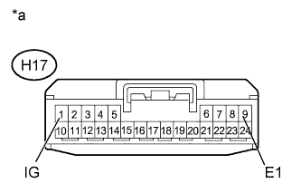
Text in Illustration*a
| Front view of wire harness connector
(to Headlight Leveling ECU Assembly)
|
| | REPAIR OR REPLACE HARNESS OR CONNECTOR |
|
|