Lighting System -- Terminals Of Ecu |
| CHECK HEADLIGHT LEVELING ECU (for HID Headlight) |

Disconnect the H17 headlight leveling ECU connector.
Measure the voltage and resistance according to the value(s) in the table below.
If the result is not as specified, there may be a malfunction on the wire harness side.Terminal No. (Symbol) Wiring Color Terminal Description Condition Specified Condition H17-1 (IG) - Body ground R-L - Body ground*1
B - Body ground*2Ignition power supply Ignition switch off Below 1 V Ignition switch ON 11 to 14 V H17-9 (E1) - Body ground GR - Body ground Ground Always Below 1 Ω Reconnect the H17 headlight leveling ECU connector.
Measure the resistance and voltage according to the value(s) in the table below.
Terminal No. (Symbol) Wiring Color Terminal Description Condition Specified Condition H17-3 (B2) - H17-9 (E1) P - GR Low beam headlight signal input Low beam headlights on Below 1 V Low beam headlights off 11 to 14 V H17-5 (SPDL) - H17-9 (E1) V - GR Initialization signal input Terminal LVL and terminal CG of DLC3 connected Below 1 V Terminal LVL and terminal CG of DLC3 not connected 4.5 to 5.5 V H17-6 (WNG) - H17-9 (E1) B-L - GR Warning indicator drive output Warning indicator on Below 1 V Warning indicator off 11 to 14 V H17-10 (RH+) - H17-9 (E1) R - GR Leveling motor RH power supply Ignition switch off Below 1 V Ignition switch ON 11 to 14 V H17-11 (LH+) - H17-9 (E1) Y - GR Leveling motor LH power supply Ignition switch off Below 1 V Ignition switch ON 11 to 14 V H17-12 (SBR) - H17-21 (SGR) B - G Rear height control sensor power supply Ignition switch off Below 1 V Ignition switch ON 4.75 to 5.25 V H17-16 (SPDR) - H17-9 (E1) L - GR Vehicle speed signal input Vehicle is driven at approximately 20 km/h (12 mph) Pulse generation
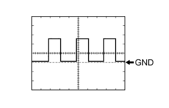
(See waveform 1)H17-17 (RHE) - H17-9 (E1) LG - GR Leveling motor RH operation signal input With low beam headlights on, vehicle height not changed Below 1 V With low beam headlights on, vehicle height changed and maintained for more than 3 seconds 1.0 to 14.4 V H17-18 (LHE) - H17-9 (E1) W - GR Leveling motor LH operation signal input With low beam headlights on, vehicle height not changed Below 1 V With low beam headlights on, vehicle height changed and maintained for more than 3 seconds 1.0 to 14.4 V H17-19 (SHRL) - H17-21 (SGR) L - G Rear height control sensor signal input Ignition switch off Below 1 V Ignition switch ON 0.5 to 4.5 V H17-21 (SGR) - H17-9 (E1) G - GR Rear height control sensor ground Always Below 1 Ω H17-23 (RH-) - H17-9 (E1) B-O - GR Leveling motor RH ground Always Below 1 Ω H17-24 (LH-) - H17-9 (E1) GR - GR Leveling motor LH ground Always Below 1 Ω - *1: w/ Automatic Light Control System
- *2: w/o Automatic Light Control System
Waveform 1
Item Content Terminal No. (Symbol) H17-16 (SPDR) - H17-9 (E1) Tool setting 5 V/DIV., 20 ms./DIV. Condition Vehicle is driven at approximately 20 km/h (12 mph) - HINT:
- As the vehicle speed increases, the wavelength shortens.
- *1: w/ Automatic Light Control System
| CHECK AUTOMATIC LIGHT CONTROL SENSOR (w/ Automatic Light Control System) |

Disconnect the A39 automatic light control sensor connector.
Measure the voltage and resistance according to the value(s) in the table below.
If the result is not as specified, there may be a malfunction on the wire harness side.Terminal No. (Symbol) Wiring Color Terminal Description Condition Specified Condition A39-1 (IG) - Body ground R-L - Body ground Ignition power supply Ignition switch off Below 1 V Ignition switch ON 11 to 14 V A39-2 (B) - Body ground L-Y - Body ground Battery power supply Always 11 to 14 V A39-6 (A) - Body ground P-L - Body ground Ground Headlight dimmer switch in AUTO position Below 1 Ω Headlight dimmer switch not in AUTO position 10 kΩ or higher Reconnect the A39 automatic light control sensor connector.
Measure the voltage according to the value(s) in the table below.
If the result is not as specified, the automatic light control sensor may have a malfunction.Terminal No. (Symbol) Wiring Color Terminal Description Condition Specified Condition A39-3 (CTY) - Body ground R-B - Body ground Front door courtesy light switch (driver side) signal input Driver side door open Below 1 V Driver side door closed 11 to 14 V A39-5 (H) - Body ground GR - Body ground H-LP RLY relay drive output Ignition switch ON
Headlight dimmer switch in AUTO position
Automatic light control sensor covered with a hand
Low beam headlights come onBelow 1 V Ignition switch ON
Headlight dimmer switch in AUTO position
Automatic light control sensor exposed to ambient light
Low beam headlights turn off11 to 14 V A39-7 (T) - Body ground LG-B - Body ground Taillight relay drive output Ignition switch ON
Headlight dimmer switch in AUTO position
Automatic light control sensor covered with a hand
Taillights come onBelow 1 V Ignition switch ON
Headlight dimmer switch in AUTO position
Automatic light control sensor exposed to ambient light
Taillights turn off11 to 14 V