Theft Deterrent System Driver Side Door Courtesy Switch Circuit
DESCRIPTION
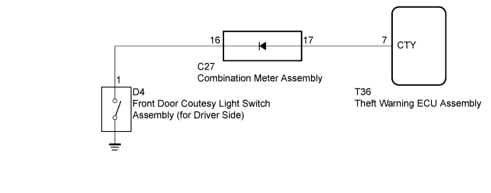
WIRING DIAGRAM
INSPECTION PROCEDURE
CHECK COMBINATION METER ASSEMBLY
CHECK HARNESS AND CONNECTOR (COMBINATION METER - THEFT WARNING ECU)
INSPECT FRONT DOOR COURTESY LIGHT SWITCH ASSEMBLY (FOR DRIVER SIDE)
CHECK HARNESS AND CONNECTOR (COMBINATION METER - FRONT DOOR COURTESY LIGHT SWITCH [FOR DRIVER SIDE])
THEFT DETERRENT SYSTEM - Driver Side Door Courtesy Switch Circuit |
DESCRIPTION
The theft warning ECU assembly detects the condition of the front door courtesy light switch assembly (for Driver Side).
WIRING DIAGRAM
INSPECTION PROCEDURE
| 1.CHECK COMBINATION METER ASSEMBLY |
When the driver side door is opened/closed, check that the indicator in the combination meter assembly operates normally.
- OK:
- Indicator operates normally.
| 2.CHECK HARNESS AND CONNECTOR (COMBINATION METER - THEFT WARNING ECU) |
Disconnect the C27 combination meter assembly connector.
Disconnect the T36 theft warning ECU assembly connector.
Measure the resistance according to the value(s) in the table below.
- Standard Resistance:
Tester Connection
| Condition
| Specified Condition
|
C27-17 - T36-7 (CTY)
| Always
| Below 1 Ω
|
C27-17 or T36-7 (CTY) - Body ground
| Always
| 10 kΩ or higher
|
Measure the voltage according to the value(s) in the table below.
- Standard Voltage:
Tester Connection
| Condition
| Specified Condition
|
C27-17 - Body ground
| Always
| 11 to 14 V
|
| | REPAIR OR REPLACE HARNESS OR CONNECTOR |
|
|
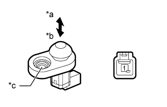
| 3.INSPECT FRONT DOOR COURTESY LIGHT SWITCH ASSEMBLY (FOR DRIVER SIDE) |
Remove the front door courtesy light switch assembly (for Driver Side) (Toyota Fortuner RM00000113X002X.html)
Measure the resistance according to the value(s) in the table below.
- Standard Resistance:
Tester Connection
| Switch Condition
| Specified Condition
|
1 - Body ground
| Not pushed (ON)
| Below 1 Ω
|
Pushed (OFF)
| 10 kΩ or higher
|
Text in Illustration*a
| Not pushed (ON)
|
*b
| Pushed (OFF)
|
*c
| Body ground
|
| 4.CHECK HARNESS AND CONNECTOR (COMBINATION METER - FRONT DOOR COURTESY LIGHT SWITCH [FOR DRIVER SIDE]) |
Disconnect the C27 combination meter assembly connector.
Disconnect the D4 front door courtesy light switch assembly (for Driver Side) connector.
Measure the resistance according to the value(s) in the table below.
- Standard Resistance:
Tester Connection
| Condition
| Specified Condition
|
C27-16 - D4-1
| Always
| Below 1 Ω
|
C27-16 or D4-1 - Body ground
| Always
| 10 kΩ or higher
|
| | REPAIR OR REPLACE HARNESS OR CONNECTOR |
|
|