Theft Deterrent System Security Indicator Light Circuit
DESCRIPTION
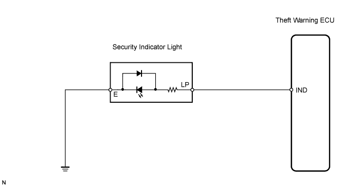
WIRING DIAGRAM
INSPECTION PROCEDURE
INSPECT SECURITY INDICATOR LIGHT ASSEMBLY
CHECK WIRE HARNESS (SECURITY INDICATOR LIGHT - THEFT WARNING ECU AND BODY GROUND)
THEFT DETERRENT SYSTEM - Security Indicator Light Circuit |
DESCRIPTION
When the theft deterrent system is in the disarmed state, the security indicator light will flash continuously if the immobiliser system is set, or not illuminate if the immobiliser system is not set.When the theft deterrent system is in the armed state, the immobiliser system is automatically set and the security indicator light will flash continuously.When the theft deterrent system is in the arming preparation state or alarm sounding state, the theft warning ECU causes the security indicator light to illuminate.
WIRING DIAGRAM
INSPECTION PROCEDURE
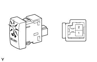
| 1.INSPECT SECURITY INDICATOR LIGHT ASSEMBLY |
Remove the security indicator light.
Apply battery voltage between the terminals of the security indicator light, and check the illumination of the security indicator light.
- OK:
Measurement Condition
| Specified Condition
|
Battery positive (+) → Terminal 2
Battery negative (-) → Terminal 1
| Illuminates
|
- NOTICE:
- If the positive (+) lead and the negative (-) lead are incorrectly connected, the security indicator light will not illuminate.
- If the voltage is too low, the security indicator light will not illuminate.
| | REPLACE SECURITY INDICATOR LIGHT ASSEMBLY |
|
|
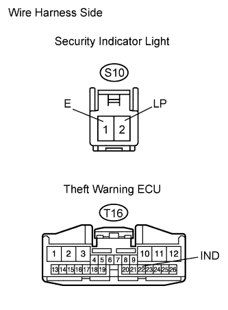
| 2.CHECK WIRE HARNESS (SECURITY INDICATOR LIGHT - THEFT WARNING ECU AND BODY GROUND) |
Disconnect the S10 indicator connector.
Disconnect the T16 ECU connector.
Measure the resistance of the wire harness side connectors.
- Standard resistance:
Tester Connection
| Specified Condition
|
T16-22 (IND) - S10-2 (LP)
| Below 1 Ω
|
T16-22 (IND) or S10-2 (LP) - Body ground
| 10 kΩ or higher
|
S10-1 (E) - Body ground
| Below 1 Ω
|
| | REPAIR OR REPLACE HARNESS AND CONNECTOR |
|
|
| OK |
|
|
|
| PROCEED TO NEXT CIRCUIT INSPECTION SHOWN IN PROBLEM SYMPTOMS TABLE |
|