CHECK FRONT PASSENGER AIRBAG ASSEMBLY (PASSENGER SQUIB)
CHECK INSTRUMENT PANEL WIRE (PASSENGER SQUIB CIRCUIT)
CHECK NO. 2 INSTRUMENT PANEL WIRE
DTC B1805/52 Short in Front Passenger Side Squib Circuit |
DTC B1806/52 Open in Front Passenger Side Squib Circuit |
DTC B1807/52 Short to GND in Front Passenger Side Squib Circuit |
DTC B1808/52 Short to B+ in Front Passenger Side Squib Circuit |
SYSTEM DESCRIPTION
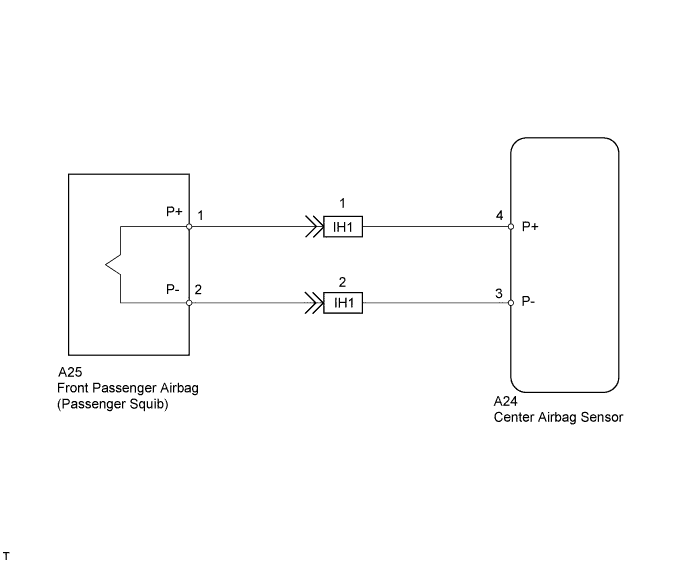
The front passenger side squib circuit consists of the center airbag sensor and front passenger airbag. The circuit instructs the SRS to deploy when deployment conditions are met. These DTCs are recorded when a malfunction is detected in the front passenger side squib circuit.| DTC No. | DTC Detection Condition | Trouble Area |
| B1805/52 | Center airbag sensor receives line short circuit signal 5 times in passenger squib circuit during primary check |
|
| B1806/52 | Center airbag sensor receives open circuit signal in passenger squib circuit for 2 seconds |
|
| B1807/52 | Center airbag sensor receives short circuit to ground signal in passenger squib circuit for 0.5 seconds |
|
| B1808/52 | Center airbag sensor receives B+ short circuit signal in passenger squib circuit for 0.5 seconds |
|
WIRING DIAGRAM
INSPECTION PROCEDURE
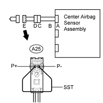
| 1.CHECK FRONT PASSENGER AIRBAG ASSEMBLY (PASSENGER SQUIB) |
 |
Turn the ignition switch OFF.
Disconnect the cable from the negative (-) battery terminal, and wait for at least 90 seconds.
Disconnect the connector from the front passenger airbag.
Connect the white wire side of SST (resistance 2.1 Ω) to the instrument panel wire connector E.
- SST
- 09843-18060
- CAUTION:
- Never connect a tester to the front passenger airbag (passenger squib) for measurement, as this may lead to a serious injury due to airbag deployment.
- NOTICE:
- Do not forcibly insert SST into the terminals of the connector when connecting.
- Insert SST straight into the terminals of the connector.
Connect the cable to the negative (-) battery terminal, and wait for at least 2 seconds.
Turn the ignition switch ON, and wait for at least 60 seconds.
Clear the DTCs (Toyota Fortuner RM000000YVY004X.html).
Turn the ignition switch OFF.
Turn the ignition switch ON, and wait for at least 60 seconds.
Check for DTCs (Toyota Fortuner RM000000YVY004X.html).
- OK:
- DTC B1805, B1806, B1807, B1808 or 52 is not output.
- HINT:
- DTCs other than DTC B1805, B1806, B1807, B1808 or 52 may be output at this time, but they are not related to this check.
|
| ||||
| NG | |
| 2.CHECK CONNECTOR |
Turn the ignition switch OFF.
Disconnect the cable from the negative (-) battery terminal, and wait for at least 90 seconds.
Disconnect SST (resistance 2.1 Ω) from the instrument panel wire.
Check that the instrument panel wire connectors (on the front passenger side airbag) are not damaged.
- OK:
- Lock button is not disengaged, and claw of lock is not deformed or damaged.
|
| ||||
| OK | |
| 3.CHECK INSTRUMENT PANEL WIRE (PASSENGER SQUIB CIRCUIT) |
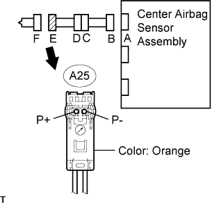 |
Disconnect the connector from the center airbag sensor.
Connect the cable to the negative (-) battery terminal, and wait for at least 2 seconds.
Turn the ignition switch ON.
Measure the voltage of the wire harness side connector.
- Standard voltage:
Tester Connection Specified Condition A25-1 (P+) - Body ground Below 1 V A25-2 (P-) - Body ground Below 1 V
Turn the ignition switch OFF.
Disconnect the cable from the negative (-) battery terminal, and wait for at least 90 seconds.
Measure the resistance of the wire harness side connector.
- Standard resistance:
Tester Connection Specified Condition A25-1 (P+) - A25-2 (P-) Below 1 Ω A25-1 (P+) - Body ground 1 MΩ or higher A25-2 (P-) - Body ground 1 MΩ or higher
Release the activation prevention mechanism built into connector B (Toyota Fortuner RM000000YVX004X.html).
Measure the resistance of the wire harness side connector.
- Standard resistance:
Tester Connection Specified Condition A25-1 (P+) - A25-2 (P-) 1 MΩ or higher
|
| ||||
| NG | |
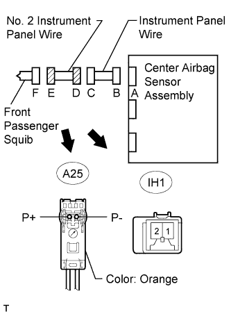
| 4.CHECK NO. 2 INSTRUMENT PANEL WIRE |
 |
Restore the released activation prevention mechanism of connector B to its original position.
Disconnect the No. 2 instrument panel wire connector from the instrument panel wire.
Connect the cable to the negative (-) battery terminal, and wait for at least 2 seconds.
Turn the ignition switch ON.
Measure the voltage of the wire harness side connector.
- Standard voltage:
Tester Connection Specified Condition A25-1 (P+) - Body ground Below 1 V A25-2 (P-) - Body ground Below 1 V
Turn the ignition switch OFF.
Disconnect the cable from the negative (-) battery terminal, and wait for at least 90 seconds.
Measure the resistance of the wire harness side connector.
- Standard resistance:
Tester Connection Specified Condition A25-1 (P+) - A25-2 (P-) Below 1 Ω A25-1 (P+) - Body ground 1 MΩ or higher A25-2 (P-) - Body ground 1 MΩ or higher
Release the activation prevention mechanism built into connector D (Toyota Fortuner RM000000YVX004X.html).
Measure the resistance of the wire harness side connector.
- Standard resistance:
Tester Connection Specified Condition A25-1 (P+) - A25-2 (P-) 1 MΩ or higher
|
| ||||
| OK | ||
| ||