Air Conditioning System (For Automatic Air Conditioning System) Compressor Circuit
DESCRIPTION
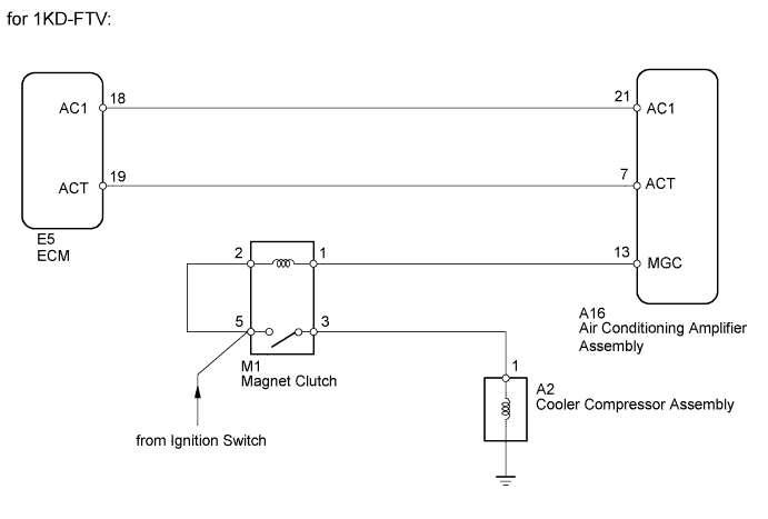
WIRING DIAGRAM
INSPECTION PROCEDURE
READ VALUE USING INTELLIGENT TESTER (A/C Signal)
INSPECT MAGNET CLUTCH RELAY
CHECK HARNESS AND CONNECTOR (AIR CONDITIONING AMPLIFIER - BATTERY)
CHECK AIR CONDITIONING AMPLIFIER ASSEMBLY (MGC VOLTAGE)
INSPECT COOLER COMPRESSOR ASSEMBLY (MAGNET CLUTCH ASSEMBLY)
CHECK HARNESS AND CONNECTOR (COOLER COMPRESSOR ASSEMBLY - MAGNET CLUTCH RELAY)
CHECK HARNESS AND CONNECTOR (AIR CONDITIONING AMPLIFIER - ECM)
CHECK AIR CONDITIONING AMPLIFIER ASSEMBLY (AC1 VOLTAGE)
CHECK AIR CONDITIONING AMPLIFIER ASSEMBLY (ACT VOLTAGE)
AIR CONDITIONING SYSTEM (for Automatic Air Conditioning System) - Compressor Circuit |
DESCRIPTION
The air conditioning amplifier outputs the magnet clutch ON signal from terminal AC1 to the ECM. The ECM receives this signal and sends a signal from terminal ACT to the magnet clutch relay, turning the magnet clutch ON.
WIRING DIAGRAM
INSPECTION PROCEDURE
| 1.READ VALUE USING INTELLIGENT TESTER (A/C Signal) |
Use the Data List to check if the A/C system is functioning properly.
ECMTester Display
| Measurement Item/Range
| Normal Condition
| Diagnostic Note
|
A/C Signal
| A/C signal / ON or OFF
| ON: A/C ON
OFF: A/C OFF
| -
|
- OK:
- Display is as specified in normal condition.
| 2.INSPECT MAGNET CLUTCH RELAY |
Remove the magnet clutch relay.
Measure the resistance according to the value(s) in the table below.
- Standard Resistance:
Tester Connection
| Condition
| Specified Condition
|
3 - 5
| Battery voltage is not applied to terminals 1 and 2
| 10 kΩ or higher
|
Battery voltage is applied to terminals 1 and 2
| Below 1 Ω
|
| | REPLACE MAGNET CLUTCH RELAY |
|
|
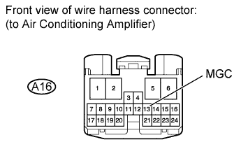
| 3.CHECK HARNESS AND CONNECTOR (AIR CONDITIONING AMPLIFIER - BATTERY) |
Disconnect the A16 amplifier connector.
Measure the voltage according to the value(s) in the table below.
- Standard Voltage:
Tester Connection
| Switch Condition
| Specified Condition
|
A16-13 (MGC) - Body ground
| Ignition switch ON
| 11 to 14 V
|
| | REPAIR OR REPLACE HARNESS OR CONNECTOR |
|
|
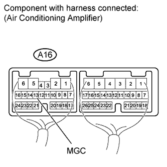
| 4.CHECK AIR CONDITIONING AMPLIFIER ASSEMBLY (MGC VOLTAGE) |
Remove the air conditioning amplifier with its connectors still connected.
Measure the voltage according to the value(s) in the table below.
- Standard Voltage:
Tester Connection
| Switch Condition
| Specified Condition
|
A16-13 (MGC) - Body ground
| Ignition switch START
A/C switch ON
| Below 1 V
|
Ignition switch START
A/C switch OFF
| 11 to 14 V
|
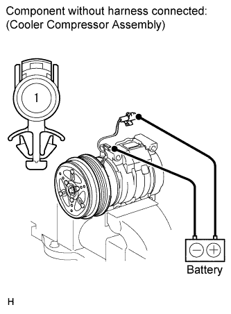
| 5.INSPECT COOLER COMPRESSOR ASSEMBLY (MAGNET CLUTCH ASSEMBLY) |
Disconnect the clutch connector.
Apply battery voltage to the clutch and check operation of the clutch.
- OK:
Measurement Connection
| Specified Condition
|
Battery positive (+) → Terminal 1
Battery negative (-) → Ground wire
| Magnet clutch engages
|
| | REPLACE COOLER COMPRESSOR ASSEMBLY (MAGNET CLUTCH ASSEMBLY) |
|
|
| 6.CHECK HARNESS AND CONNECTOR (COOLER COMPRESSOR ASSEMBLY - MAGNET CLUTCH RELAY) |
Disconnect the A2 compressor connector.
Remove the magnet clutch relay.
Measure the resistance according to the value(s) in the table below.
- Standard Resistance:
Tester Connection
| Condition
| Specified Condition
|
A2-1 - M1-3
| Always
| Below 1 Ω
|
| | REPAIR OR REPLACE HARNESS OR CONNECTOR |
|
|
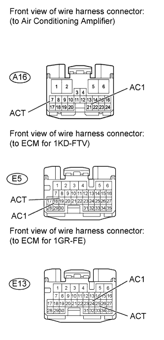
| 7.CHECK HARNESS AND CONNECTOR (AIR CONDITIONING AMPLIFIER - ECM) |
Disconnect the A16 amplifier connector.
Disconnect the E5*1 or E13*2 ECM connector.
- *1: for 1KD-FTV
- *2: for 1GR-FE
Measure the resistance according to the value(s) in the table below.
- Standard Resistance:
for 1KD-FTVTester Connection
| Condition
| Specified Condition
|
A16-21 (AC1) - E5-18 (AC1)
| Always
| Below 1 Ω
|
A16-7 (ACT) - E5-19 (ACT)
|
for 1GR-FETester Connection
| Condition
| Specified Condition
|
A16-21 (AC1) - E13-24 (AC1)
| Always
| Below 1 Ω
|
A16-7 (ACT) - E13-25 (ACT)
|
| | REPAIR OR REPLACE HARNESS OR CONNECTOR |
|
|
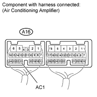
| 8.CHECK AIR CONDITIONING AMPLIFIER ASSEMBLY (AC1 VOLTAGE) |
Remove the air conditioning amplifier with its connectors still connected.
Measure the voltage according to the value(s) in the table below.
- Standard Voltage:
Tester Connection
| Switch Condition
| Specified Condition
|
A16-21 (AC1) - Body ground
| Ignition switch START
A/C switch AUTO
Magnet clutch is engaged
| Below 1 V
|
Ignition switch START
A/C switch AUTO
Magnet clutch is not engaged
| 11 to 14 V
|
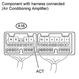
| 9.CHECK AIR CONDITIONING AMPLIFIER ASSEMBLY (ACT VOLTAGE) |
Remove the air conditioning amplifier with its connectors still connected.
Measure the voltage according to the value(s) in the table below.
- Standard Voltage:
Tester Connection
| Switch Condition
| Specified Condition
|
A16-7 (ACT) - Body ground
| Ignition switch START
A/C switch AUTO
| 11 to 14 V
|