Vane Pump (For Kd Series Engine) -- Installation |
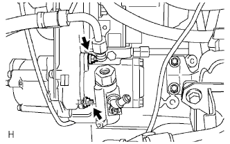
| 1. INSTALL VANE PUMP ASSEMBLY |
Coat a new O-ring with MP grease and install it to the vane pump.
Install the pump with the 2 nuts.
- Torque:
- 39 N*m{398 kgf*cm, 29 ft.*lbf}
 |
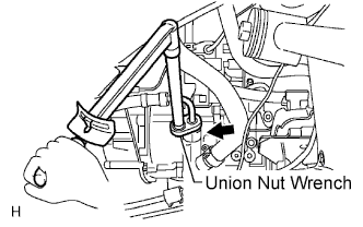
| 2. CONNECT PRESSURE FEED TUBE ASSEMBLY |
Using a union nut wrench, connect the tube to the vane pump with a new gasket and the union bolt.
- Torque:
- 44 N*m (449 kgf*cm, 33 ft.*lbf) for use without union nut wrench
40 N*m (407 kgf*cm, 30 ft.*lbf) for use with union nut wrench
 |
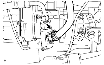
| 3. CONNECT OIL RESERVOIR TO PUMP HOSE |
Connect the oil reservoir to pump hose with the clip.
- HINT:
- Install the pump side of the hose so that the paint mark faces the front of the vehicle. Align the reservoir tank side of the hose to the tank port rib.
- Make sure the clamp's claw on the pump side faces the front of the vehicle. Also make sure the clamp's claw on the reservoir tank side faces the top of the vehicle.
 |
| 4. ADD POWER STEERING FLUID |
| 5. BLEED AIR FROM POWER STEERING SYSTEM |
| 6. CHECK POWER STEERING FLUID LEVEL IN RESERVOIR |
| 7. INSPECT FOR FLUID LEAKS |
| 8. INSTALL FRONT SIDE MEMBER TO FRONT SUSPENSION CROSSMEMBER BRACE |
Install the crossmember brace with the 8 bolts.
- Torque:
- 50 N*m{510 kgf*cm, 37 ft.*lbf}
| 9. INSTALL NO. 1 ENGINE UNDER COVER |
Install the engine under cover with the 4 bolts.
- Torque:
- 28 N*m{286 kgf*cm, 21 ft.*lbf}
| 10. INSTALL NO. 2 ENGINE UNDER COVER |
Install the engine under cover with the 4 bolts.
- Torque:
- 28 N*m{286 kgf*cm, 21 ft.*lbf}