Deceleration Sensor (W/ Abs) -- On-Vehicle Inspection |
| 1. CHECK DECELERATION SENSOR |
Disconnect the sensor connector.
Connect 3 dry cell batteries of 1.5 V in series.
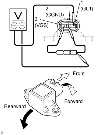 |
Connect the batteries' positive (+) lead to terminal 3 (VGS) and the negative (-) lead to terminal 2 (GGND).
Connect the voltmeter's positive (+) lead to the negative (-) lead of the batteries, and the negative (-) lead to terminal 1 (GL1). Apply approximately 4.5 V.
- HINT:
- Do not apply 6 V or more to terminals 3 (VGS) and 2 (GGND).
Check the output voltage of terminal 1 (GL1) when the sensor is tilted forward and rearward.
- Standard voltage:
Tester Connection Sensor Position Specified Condition 1 (GL1) - Battery's negative (-) lead Horizontal Approx. 2.5 V 1 (GL1) - Battery's negative (-) lead Tilted forward Approx. 0.5 to 2.5 V 1 (GL1) - Battery's negative (-) lead Tilted rearward Approx. 2.5 to 4.5 V
- HINT:
- When replacing the sensor, do not place the new sensor upside down.
Connect the sensor connector.