Dtc C1232 Acceleration Sensor Stuck Malfunction
DESCRIPTION
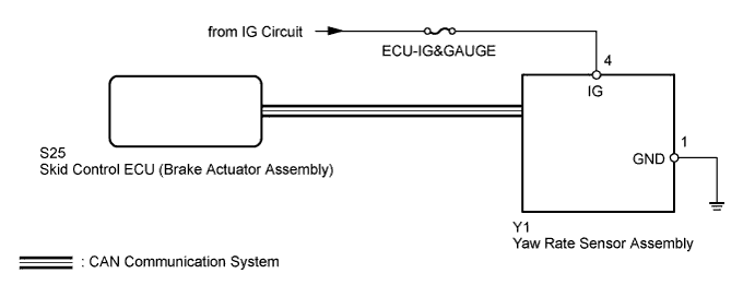
WIRING DIAGRAM
INSPECTION PROCEDURE
CHECK DTC
CHECK YAW RATE SENSOR ASSEMBLY INSTALLATION
CHECK TERMINAL VOLTAGE AND RESISTANCE (IG, GND TERMINAL)
DTC C1232 Acceleration Sensor Stuck Malfunction |
DTC C1243 Acceleration Sensor Stuck Malfunction |
DTC C1245 Acceleration Sensor Output Malfunction |
DTC C1279 Acceleration Sensor Output Voltage Malfunction (Test Mode DTC) |
DESCRIPTION
The skid control ECU (brake actuator assembly) receives signals from the yaw rate assembly via the CAN communication system.The yaw rate sensor assembly has a built-in acceleration sensor and detects the vehicle's condition using 2 circuits (GL1, GL2).If there is trouble in the bus lines between the yaw rate sensor assembly and the CAN communication system, DTCs U0123 (Lost Communication with Yaw Rate Sensor Module) and U0124 (Lost Communication with Lateral Acceleration Sensor Module) are stored.DTC C1232, C1243, C1245 and C1279 are also stored when calibration has not been completed.DTC C1279 can be cleared when the yaw rate sensor assembly sends a yaw rate and/or acceleration signal or Test Mode ends. DTC C1279 is stored only in Test Mode.DTC Code
| DTC Detection Condition
| Trouble Area
|
C1232
| At a vehicle speed of 10 km/h (6 mph) or more, either GL1 or GL2 (input signal) does not change for 30 seconds or more.
| - Acceleration sensor (Yaw rate sensor assembly)
- Yaw rate sensor assembly circuit
|
C1243
| While the vehicle speed changes from 30 km/h (19 mph) to 0 km/h (0 mph), the condition that the values of GL1 and GL2 do not change by 0.0294 G or more occurs 16 times or more.
| - Acceleration sensor (Yaw rate sensor assembly)
- Yaw rate sensor assembly circuit
|
C1245
| At a vehicle speed of 30 km/h (19 mph) or more, the difference between the forward and backward G calculated from the acceleration sensor value and that calculated from the vehicle speed exceeds 0.35 G for 60 seconds or more.
| - Acceleration sensor (Yaw rate sensor assembly)
- Yaw rate sensor assembly circuit
- Sensor installation
|
C1279
| Stored during Test Mode.
| - Acceleration sensor (Yaw rate sensor assembly)
- Sensor installation
|
WIRING DIAGRAM
INSPECTION PROCEDURE
- NOTICE:
- After replacing the yaw rate sensor assembly, perform calibration (Toyota Fortuner RM000000XHR06WX.html).
- Inspect the fuses for circuits related to this system before performing the following inspection procedure.
- Before disconnecting the connector, make sure that there are no problems with the connection.
- After disconnecting the connector, make sure that the connector case and terminals are not deformed or corroded.
- HINT:
- When DTC U0123 and/or U0124 is output together with DTC C1232, C1243 and/or C1245, inspect and repair the trouble areas indicated by DTC U0123 and/or U0124 first (Toyota Fortuner RM000000YUO0DYX.html).
Clear the DTCs (Toyota Fortuner RM000000XHV0C7X.html).
Turn the ignition switch off.
Start the engine.
Drive the vehicle at a speed of 30 km/h (19 mph) or more, turn the steering wheel and decelerate (depress the brake pedal) the vehicle.
Turn the ignition switch off.
Turn the ignition switch to ON again and check that no CAN communication system DTC is output (Toyota Fortuner RM000000XHV0C7X.html).
Check if DTCs for zero point calibration of the yaw rate sensor (C1210) or for zero point calibration of the acceleration sensor (C1336) are output (Toyota Fortuner RM000000XHV0C7X.html).
ResultResult
| Proceed to
|
DTC relating to yaw rate and acceleration sensor is output
| A
|
DTC relating to CAN communication system is output
| B
|
DTC C1210 and/or C1336 is output
| C
|
| 2.CHECK YAW RATE SENSOR ASSEMBLY INSTALLATION |
Turn the ignition switch off.
Check that the yaw rate sensor assembly is installed properly (Toyota Fortuner RM000000SS204FX.html).
- OK:
- The sensor is tightened to the specified torque.
- The sensor is not installed at an angle.
| 3.CHECK TERMINAL VOLTAGE AND RESISTANCE (IG, GND TERMINAL) |
Turn the ignition switch off.
Disconnect the yaw rate sensor assembly connector.
Measure the voltage according to the value(s) in the table below.
- Standard Voltage:
Tester Connection
| Switch Condition
| Specified Condition
|
Y1-4 (IG) - Body ground
| Ignition switch ON
| 11 to 14 V
|
Measure the resistance according to the value(s) in the table below.
- Standard Resistance:
Tester Connection
| Condition
| Specified Condition
|
Y1-1 (GND) - Body ground
| Always
| Below 1 Ω
|
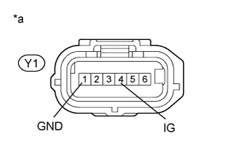
Text in Illustration*a
| Front view of wire harness connector
(to Yaw Rate Sensor Assembly)
|
| | REPAIR OR REPLACE HARNESS OR CONNECTOR |
|
|