Dtc C1381 Acceleration Sensor Power Supply Voltage Malfunction
DESCRIPTION
WIRING DIAGRAM
INSPECTION PROCEDURE
CHECK TERMINAL VOLTAGE (IG TERMINAL)
CHECK HARNESS AND CONNECTOR (GND TERMINAL)
RECONFIRM DTC
DTC C1381 Acceleration Sensor Power Supply Voltage Malfunction |
DESCRIPTION
The skid control ECU (brake actuator assembly) receives signals from the yaw rate sensor assembly via the CAN communication system.The yaw rate sensor assembly has a built-in acceleration sensor.If there is trouble in the bus lines between the yaw rate sensor and the CAN communication system, DTCs U0123 (Lost Communication with Yaw Rate Sensor Module) and U0124 (Lost Communication with Lateral Acceleration Sensor Module) are stored.DTC C1381 is also stored when calibration has not been completed.DTC Code
| DTC Detection Condition
| Trouble Area
|
C1381
| At a vehicle speed of more than 3 km/h (2 mph), the acceleration sensor power source malfunction signal is received for 10 seconds or more.
| - ECU-IG&GAUGE fuse
- Acceleration sensor (Yaw rate sensor assembly)
- Yaw rate sensor assembly power source circuit
|
WIRING DIAGRAM
Refer to DTCs C1232, C1243 and C1245 (Toyota Fortuner RM000001RFV0B3X.html).
INSPECTION PROCEDURE
- NOTICE:
- After replacing the yaw rate sensor assembly, perform calibration (Toyota Fortuner RM000000XHR06WX.html).
- Inspect the fuses for circuits related to this system before performing the following inspection procedure.
- Before disconnecting the connector, make sure that there are no problems with the connection.
- After disconnecting the connector, make sure that the connector case and terminals are not deformed or corroded.
| 1.CHECK TERMINAL VOLTAGE (IG TERMINAL) |
Turn the ignition switch off.
Disconnect the yaw rate sensor assembly connector.
Measure the voltage according to the value(s) in the table below.
- Standard Voltage:
Tester Connection
| Switch Condition
| Specified Condition
|
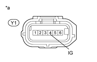
Y1-4 (IG) - Body ground
| Ignition switch ON
| 11 to 14 V
|
Text in Illustration*a
| Front view of wire harness connector
(to Yaw Rate Sensor Assembly)
|
| | REPAIR OR REPLACE HARNESS OR CONNECTOR |
|
|
| 2.CHECK HARNESS AND CONNECTOR (GND TERMINAL) |
Turn the ignition switch off.
Disconnect the yaw rate sensor assembly connector.
Measure the resistance according to the value(s) in the table below.
- Standard Resistance:
Tester Connection
| Condition
| Specified Condition
|
Y1-1 (GND) - Body ground
| Always
| Below 1 Ω
|
| | REPAIR OR REPLACE HARNESS OR CONNECTOR |
|
|
Clear the DTC (Toyota Fortuner RM000000XHV0C7X.html).
Turn the ignition switch off.
Start the engine.
Drive the vehicle at a speed of 3 km/h (2 mph) or more for at least 10 seconds.
Check if the same DTC is output (Toyota Fortuner RM000000XHV0C7X.html).
ResultResult
| Proceed to
|
DTC is not output
| A
|
DTC is output
| B
|
- HINT:
- If troubleshooting has been carried out according to Problem Symptoms Table, refer back to the table and proceed to the next suspected area (Toyota Fortuner RM000000XHN0BDX.html).