Dtc C1282 Center Differential Lock Position Switch
DESCRIPTION
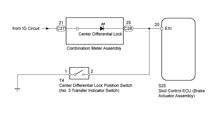
WIRING DIAGRAM
INSPECTION PROCEDURE
CHECK TERMINAL VOLTAGE (EXI TERMINAL)
CHECK TEST MODE DTC
CHECK HARNESS AND CONNECTOR (EXI CIRCUIT)
DTC C1282 Center Differential Lock Position Switch |
DESCRIPTION
DTC C1282 is stored only in Test Mode.DTC Code
| DTC Detection Condition
| Trouble Area
|
C1282
| Stored during Test Mode.
| - Harness or connector
- Transfer system
- Skid control ECU (Brake actuator assembly)
|
WIRING DIAGRAM
INSPECTION PROCEDURE
- NOTICE:
- After replacing the brake actuator assembly, perform calibration (Toyota Fortuner RM000000XHR06WX.html).
- Before disconnecting the connector, make sure that there are no problems with the connection.
- After disconnecting the connector, make sure that the connector case and terminals are not deformed or corroded.
| 1.CHECK TERMINAL VOLTAGE (EXI TERMINAL) |
Set the vehicle to the center differential lock state using the transfer shift lever.
Turn the ignition switch off.
Disconnect the skid control ECU (brake actuator assembly) connector.
Measure the voltage according to the value(s) in the table below.
- Standard Voltage:
Tester Connection
| Condition
| Specified Condition
|
S25-20 (EXI) - Body ground
| - Ignition switch ON
- Transfer shift position HL
| Below 1.5 V
|
Connect the skid control ECU (brake actuator assembly) connector.
Set the vehicle to the center differential free state using the transfer shift lever.
Turn the ignition switch off.
Disconnect the skid control ECU (brake actuator assembly) connector.
Measure the voltage according to the value(s) in the table below.
- Standard Voltage:
Tester Connection
| Condition
| Specified Condition
|
S25-20 (EXI) - Body ground
| - Ignition switch ON
- Transfer shift position H
| 11 to 14 V
|
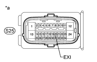
Text in Illustration*a
| Front view of wire harness connector
(to Skid Control ECU [Brake Actuator Assembly])
|
Switch the vehicle to Test Mode, check the H to LL shift operation, and then check that Test Mode DTC C1282 is cleared (Toyota Fortuner RM000000XHT08TX.html).
ResultResult
| Proceed to
|
Test Mode DTC is not cleared
| A
|
Test Mode DTC is cleared
| B
|
| 3.CHECK HARNESS AND CONNECTOR (EXI CIRCUIT) |
Turn the ignition switch off.
Disconnect the skid control ECU (brake actuator assembly) connector.
Disconnect the center differential lock position switch (No. 3 transfer indicator switch) connector.
Disconnect the C28 combination meter connector.
Measure the resistance according to the value(s) in the table below.
- Standard Resistance:
Tester Connection
| Condition
| Specified Condition
|
S25-20 (EXI) - T4-2
| Always
| Below 1 Ω
|
S25-20 (EXI) - Body ground
| Always
| 10 kΩ or higher
|
T4-1 - Body ground
| Always
| Below 1 Ω
|
| | REPAIR OR REPLACE HARNESS OR CONNECTOR |
|
|