Anti-Lock Brake System Ts And Cg Terminal Circuit
DESCRIPTION
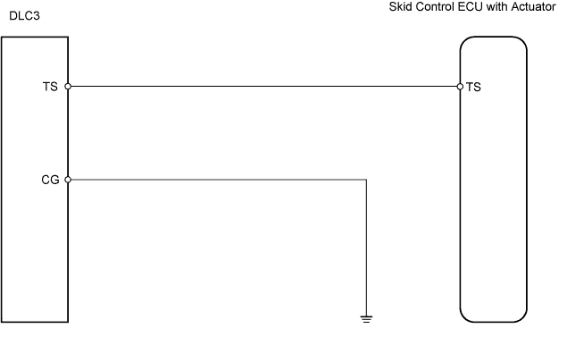
WIRING DIAGRAM
INSPECTION PROCEDURE
CHECK WIRE HARNESS (DLC3 - SKID CONTROL ECU AND BODY GROUND)
ANTI-LOCK BRAKE SYSTEM - TS and CG Terminal Circuit |
DESCRIPTION
If the vehicle is stationary during sensor check mode, speed sensor malfunctions cannot be detected. The vehicle must be driven for speed sensor malfunctions to be detected.- HINT:
- Change to sensor check mode by connecting terminals TS and CG of the DLC3, and turning the ignition switch from OFF to ON.
WIRING DIAGRAM
INSPECTION PROCEDURE
| 1.CHECK WIRE HARNESS (DLC3 - SKID CONTROL ECU AND BODY GROUND) |
Disconnect the S2 ECU connector.
Measure the resistance of the wire harness side connectors.
- Standard resistance:
Tester Connection
| Specified Condition
|
D3-4 (CG) - Body ground
| Below 1 Ω
|
D3-12 (TS) - S2-15 (TS)
| Below 1 Ω
|
S2-15 (TS) - Body ground
| 10 kΩ or higher
|
| | REPAIR OR REPLACE HARNESS AND CONNECTOR |
|
|
| OK |
|
|
|
| REPLACE BRAKE ACTUATOR ASSEMBLY |
|