Front Wheel Alignment -- Adjustment |
| 1. INSPECT TIRE |
Inspect the tires (Toyota Fortuner RM0000010MW006X.html).
| 2. INSPECT VEHICLE HEIGHT |
 |
- NOTICE:
- Before inspecting the wheel alignment, adjust the vehicle height to the specification.
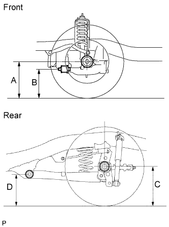
Press down on the vehicle several times to stabilize the suspension, and measure the vehicle height.
- Standard vehicle height (for unloaded vehicle):
Vehicle Model Front A - B Rear C - D GGN50R-NKMSKN 73 mm (2.87 in.) 56 mm (2.20 in.) GGN50R-NKASKN 76 mm (2.99 in.) 57 mm (2.17 in.) GGN60R-NKMSKN 74 mm (2.91 in.) 55 mm (2.17 in.) KUN51R-NKMSYN 76 mm (2.99 in.) 57 mm (2.17 in.) KUN51L-NKMSYN 76 mm (2.99 in.) 59 mm (2.32 in.) KUN61R-NKMSYN 74 mm (2.91 in.) 56 mm (2.20 in.) TGN51L-NKMSKN 73 mm (2.87 in.) 55 mm (2.17 in.) LAN50R-NKMSEN 74 mm (2.91 in.) 56 mm (2.20 in.) LAN50L-NKMSEN 74 mm (2.91 in.) 57 mm (2.17 in.)
- Measuring point:
- A:
- Ground clearance of front wheel center
- B:
- Ground clearance of lower suspension arm No. 1 set bolt center
- C:
- Ground clearance of rear wheel center
- D:
- Ground clearance of strut rod set bolt center
- If the vehicle height is not as specified, press down on the vehicle several times to stabilize the suspension. Then measure the vehicle height again.
| 3. INSPECT TOE-IN |
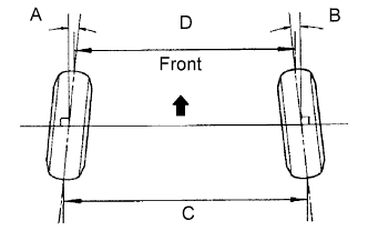 |
- Standard toe-in (for unloaded vehicle):
Vehicle Model Front A + B
Rear C - DGGN50R-NKMSKN A + B: 0°02' +-5' (0.04° +-0.09°)
C - D: 1.0 +-1.0 mm (0.04 +-0.04 in.)GGN50R-NKASKN A + B: 0°01' +-5' (0.02° +-0.09°)
C - D: 0.5 +-1.0 mm (0.02 +-0.04 in.)GGN60R-NKMSKN A + B: 0°02' +-5' (0.03° +-0.09°)
C - D: 0.8 +-1.0 mm (0.03 +-0.04 in.)KUN51R-NKMSYN A + B: 0°02' +-5' (0.03° +-0.09°)
C - D: 0.6 +-1.0 mm (0.02 +-0.04 in.)KUN51L-NKMSYN A + B: 0°01' +-5' (0.02° +-0.09°)
C - D: 0.5 +-1.0 mm (0.02 +-0.04 in.)KUN61R-NKMSYN A + B: 0°02' +-5' (0.03° +-0.09°)
C - D: 0.9 +-1.0 mm (0.04 +-0.04 in.)TGN51L-NKMSKN A + B: 0°02' +-5' (0.04° +-0.09°)
C - D: 1.1 +-1.0 mm (0.04 +-0.04 in.)LAN50R-NKMSEN A + B: 0°02' +-5' (0.04° +-0.09°)
C - D: 0.9 +-1.0 mm (0.04 +-0.04 in.)LAN50L-NKMSEN A + B: 0°02' +-5' (0.03° +-0.09°)
C - D: 0.8 +-1.0 mm (0.03 +-0.04 in.)
- If the toe-in is not as specified, adjust it at the rack ends.
| 4. ADJUST TOE-IN |
Release the rack boot set clips.
Loosen the tie rod end lock nuts.
Turn the right and left rack ends by an equal amount to adjust the toe-in to the center value.
- HINT:
- The toe-in should be as close as possible to the center value.
Make sure that the length of the right and left rack ends are approximately the same.
- Standard difference:
- 0 +-1 mm (0 +-0.039 in.)
 |
Tighten the tie rod end lock nuts.
- Torque:
- 55.5 N*m{566 kgf*cm, 41 ft.*lbf}
Place the boots on the seats and install the clips.
- HINT:
- Make sure that the boots are not twisted.
| 5. INSPECT WHEEL ANGLE |
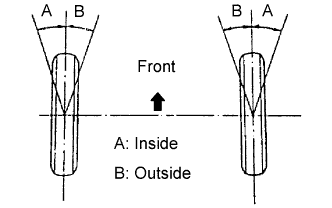 |
Turn the steering wheel to the left and right full lock positions, and measure the turning angle.
- Standard wheel angle (for unloaded vehicle):
Inside wheel angle Outside wheel angle (reference) 36°18' (34°18' to 37°18')
(36.30° (34.30° to 37.30°))33°12'
(33.20°)
- If the angles are not as specified, check and adjust the right and left rack end lengths.
| 6. INSPECT CAMBER, CASTER AND STEERING AXIS INCLINATION |
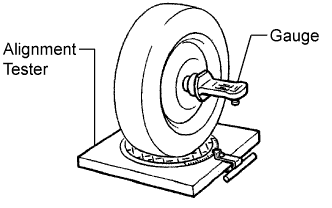 |
Install the camber-caster-kingpin gauge or place the front wheels on the center of the wheel alignment tester.
Inspect the camber, caster and steering axis inclination.
- Standard camber inclination (for unloaded vehicle):
Vehicle Model Camber Inclination GGN50R-NKMSKN
Right-left error0°14' +-30' (0.23° +-0.50°)
30' (0.50°) or lessGGN50R-NKASKN
Right-left error0°10' +-30' (0.17° +-0.50°)
30' (0.50°) or lessGGN60R-NKMSKN
Right-left error0°12' +-30' (0.20° +-0.50°)
30' (0.50°) or lessKUN51R-NKMSYN
Right-left error0°11' +-30' (0.18° +-0.50°)
30' (0.50°) or lessKUN51L-NKMSYN
Right-left error0°10' +-30' (0.17° +-0.50°)
30' (0.50°) or lessKUN61R-NKMSYN
Right-left error0°13' +-30' (0.22° +-0.50°)
30' (0.50°) or lessTGN51L-NKMSKN
Right-left error0°14' +-30' (0.23° +-0.50°)
30' (0.50°) or lessLAN50R-NKMSEN
Right-left error0°13' +-30' (0.22° +-0.50°)
30' (0.50°) or lessLAN50L-NKMSEN
Right-left error0°13' +-30' (0.22° +-0.50°)
30' (0.50°) or less
- Standard caster inclination (for unloaded vehicle):
Vehicle Model Caster Inclination GGN50R-NKMSKN
Right-left error2°46' +-30' (2.77° +-0.50°)
30' (0.50°) or lessGGN50R-NKASKN
Right-left error2°48' +-30' (2.80° +-0.50°)
30' (0.50°) or lessGGN60R-NKMSKN
Right-left error2°48' +-30' (2.80° +-0.50°)
30' (0.50°) or lessKUN51R-NKMSYN
Right-left error2°48' +-30' (2.80° +-0.50°)
30' (0.50°) or lessKUN51L-NKMSYN
Right-left error2°50' +-30' (2.83° +-0.50°)
30' (0.50°) or lessKUN61R-NKMSYN
Right-left error2°47' +-30' (2.78° +-0.50°)
30' (0.50°) or lessTGN51L-NKMSKN
Right-left error2°46' +-30' (2.77° +-0.50°)
30' (0.50°) or lessLAN50R-NKMSEN
Right-left error2°44' +-30' (2.73° +-0.50°)
30' (0.50°) or lessLAN50L-NKMSEN
Right-left error2°46' +-30' (2.77° +-0.50°)
30' (0.50°) or less
- Standard steering axis inclination (for unloaded vehicle):
Vehicle Model Steering Axis Inclination GGN50R-NKMSKN
Right-left error12°15' +-30' (12.25° +-0.50°)
30' (0.50°) or lessGGN50R-NKASKN
Right-left error12°19' +-30' (12.32° +-0.50°)
30' (0.50°) or lessGGN60R-NKMSKN
Right-left error12°16' +-30' (12.27° +-0.50°)
30' (0.50°) or lessKUN51R-NKMSYN
Right-left error12°18' +-30' (12.35° +-0.50°)
30' (0.50°) or lessKUN51L-NKMSYN
Right-left error12°19' +-30' (12.32° +-0.50°)
30' (0.50°) or lessKUN61R-NKMSYN
Right-left error12°16' +-30' (12.27° +-0.50°)
30' (0.50°) or lessTGN51L-NKMSKN
Right-left error12°15' +-30' (12.25° +-0.50°)
30' (0.50°) or lessLAN50R-NKMSEN
Right-left error12°16' +-30' (12.27° +-0.50°)
30' (0.50°) or lessLAN50L-NKMSEN
Right-left error12°16' +-30' (12.27° +-0.50°)
30' (0.50°) or less
- If the camber and caster are not as specified, adjust them.
- If the steering axis inclination is not as specified after the camber and caster have been correctly adjusted, check the steering knuckle and front wheel for distortion or looseness.
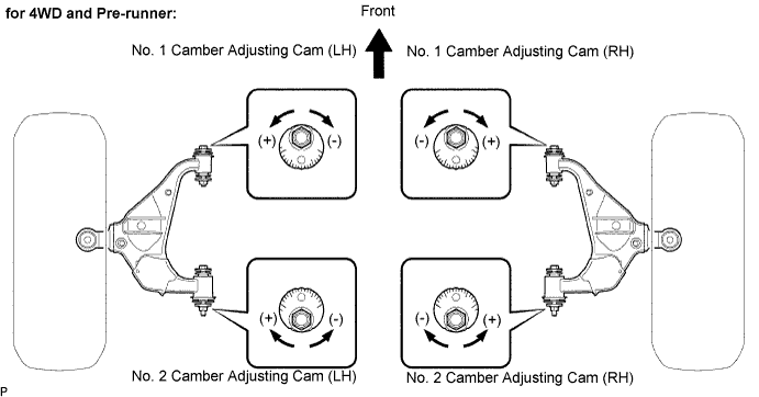
| 7. ADJUST CAMBER AND CASTER |
- NOTICE:
- After the camber has been adjusted, inspect the toe-in.
Loosen the camber adjusting cam nut and camber adjusting cam bolt.
Turn the No. 1 camber adjusting cam and No. 2 camber adjusting cam in both directions, and adjust the camber and caster to the center value.
- HINT:
- The camber and caster should be as close as possible to the center value.
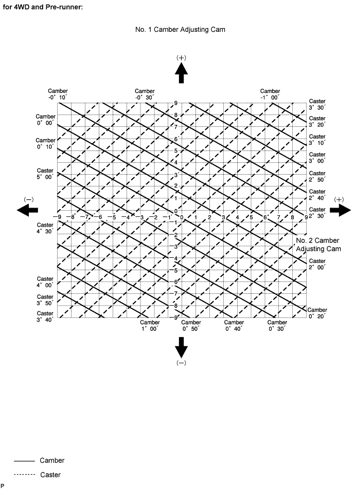
How to read adjustment chart (using examples).
Find the wheel alignment standard value applicable for the particular model.
Mark the selected standard value on the adjustment chart.
- Standard value (reference):
Camber Caster 0°00' (0.00°) 4°20' (4.30°)
Mark the alignment value measured when the vehicle is unloaded on the adjustment chart.
- Measured value (reference):
Camber Caster 0°10' (0.00°) 3°50' (3.83°)
As shown in the chart, read the distance from the marked point to 0, and adjust the front and/or rear adjusting cams accordingly.
- Amount to turn adjusting cams (by gradation):
No. 1 camber adjusting cam No. 2 camber adjusting cam +3.0 mm -1.5 mm
 |