Rear Differential Carrier Assembly Disassembly
SECURE REAR DIFFERENTIAL CARRIER ASSEMBLY
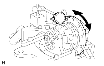
INSPECT REAR DRIVE PINION COMPANION FLANGE SUB-ASSEMBLY
INSPECT RUNOUT OF DIFFERENTIAL RING GEAR
INSPECT DIFFERENTIAL RING GEAR BACKLASH
INSPECT DIFFERENTIAL DRIVE PINION PRELOAD
INSPECT TOTAL PRELOAD
REMOVE REAR DRIVE PINION NUT
REMOVE REAR DRIVE PINION COMPANION FLANGE SUB-ASSEMBLY WITH DUST DEFLECTOR
REMOVE REAR DIFFERENTIAL CARRIER OIL SEAL
REMOVE REAR DIFFERENTIAL DRIVE PINION OIL SLINGER
REMOVE REAR DRIVE PINION FRONT TAPERED ROLLER BEARING
REMOVE REAR DIFFERENTIAL BEARING ADJUSTING NUT LOCK
REMOVE DIFFERENTIAL CASE ASSEMBLY
REMOVE DIFFERENTIAL DRIVE PINION
REMOVE REAR DRIVE PINION REAR TAPERED ROLLER BEARING
REMOVE REAR DRIVE PINION FRONT TAPERED ROLLER BEARING
REMOVE DIFFERENTIAL OIL STORAGE RING
REMOVE REAR DRIVE PINION REAR TAPERED ROLLER BEARING
REMOVE DIFFERENTIAL RING GEAR
INSPECT DIFFERENTIAL CASE ASSEMBLY RUNOUT
REMOVE REAR DIFFERENTIAL CASE BEARING
DISASSEMBLE DIFFERENTIAL CASE
INSPECT DIFFERENTIAL GEAR KIT
INSPECT DIFFERENTIAL CASE
Rear Differential Carrier Assembly -- Disassembly |
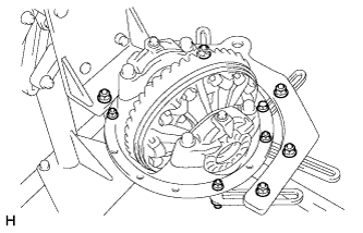
| 1. SECURE REAR DIFFERENTIAL CARRIER ASSEMBLY |
Secure the differential carrier.
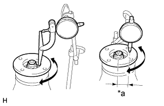
| 2. INSPECT REAR DRIVE PINION COMPANION FLANGE SUB-ASSEMBLY |
Using a dial indicator, measure the runout of the companion flange vertically and laterally.
Text in Illustration*a
| 30 mm (1.18 in.)
|
- Maximum Runout:
Item
| Specified Condition
|
Vertical runout
| 0.10 mm (0.00394 in.)
|
Lateral runout
| 0.10 mm (0.00394 in.)
|
- If the runout is more than the maximum, replace the companion flange.
| 3. INSPECT RUNOUT OF DIFFERENTIAL RING GEAR |
Using a dial indicator, check the runout of the ring gear.
- Maximum runout:
- 0.07 mm (0.00276 in.)
- If the runout is more than the maximum, replace the ring gear with a new one.
| 4. INSPECT DIFFERENTIAL RING GEAR BACKLASH |
Using a dial indicator, check the backlash of the ring gear.
- Backlash:
- 0.13 to 0.18 mm (0.00512 to 0.00708 in.)
- If the backlash is not within the specification, adjust the side bearing preload or perform repairs as necessary.
- HINT:
- Perform the measurement at 3 or more positions around the circumference of the ring gear.
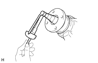
| 5. INSPECT DIFFERENTIAL DRIVE PINION PRELOAD |
Using a torque wrench, measure the preload.
- Standard Preload (Starting Torque):
Bearing
| Specified Condition
|
New
| 1.1 to 1.6 N*m (12 to 16 kgf*cm, 10 to 14 in.*lbf)
|
Reused
| 0.6 to 0.8 N*m (7 to 8 kgf*cm, 6 to 7 in.*lbf)
|
- If the result is not as specified, adjust the preload (Toyota Fortuner RM0000010MS03BX_01_0010.html).
Using a torque wrench, measure the preload with the teeth of the drive pinion and ring gear in contact.
- Standard Total Preload:
Bearing
| Specified Condition
|
New
| 0.4 to 0.5 N*m (4 to 6 kgf*cm, 4 to 5 in.*lbf) + drive pinion preload
|
Reused
| 0.4 to 0.5 N*m (4 to 6 kgf*cm, 4 to 5 in.*lbf) + drive pinion preload
|
- If the result is not as specified, adjust the preload.
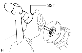
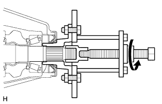
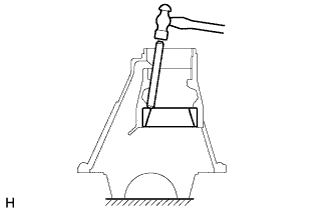
| 7. REMOVE REAR DRIVE PINION NUT |
Using SST and a hammer, loosen the staked part of the nut.
- SST
- 09930-00010(09931-00010,09931-00020)
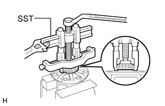
Using SST to hold the companion flange in place, remove the nut.
- SST
- 09330-00021(09330-00030)
Text in Illustration*a
| Turn
|
*b
| Hold
|
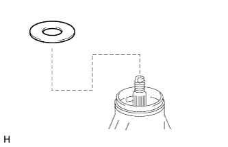
| 8. REMOVE REAR DRIVE PINION COMPANION FLANGE SUB-ASSEMBLY WITH DUST DEFLECTOR |
Using SST, remove the companion flange with dust deflector.
- SST
- 09950-30012(09951-03010,09953-03010,09954-03010,09955-03030,09956-03040)
- NOTICE:
- Before using SST (center bolt), apply hypoid gear oil to its threads and tip.
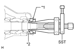
| 9. REMOVE REAR DIFFERENTIAL CARRIER OIL SEAL |
Using SST, remove the oil seal.
- SST
- 09308-10010
Text in Illustration*1
| Oil Seal
|
*2
| Oil Slinger
|
| 10. REMOVE REAR DIFFERENTIAL DRIVE PINION OIL SLINGER |
Remove the oil slinger from the drive pinion.
| 11. REMOVE REAR DRIVE PINION FRONT TAPERED ROLLER BEARING |
Using SST, remove the roller bearing (inner) from the drive pinion.
- SST
- 09556-22010
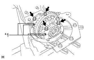
| 12. REMOVE REAR DIFFERENTIAL BEARING ADJUSTING NUT LOCK |
Remove the 2 bolts and 2 adjusting nut locks.
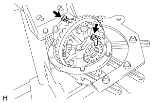
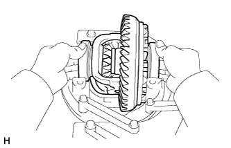
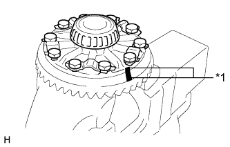
| 13. REMOVE DIFFERENTIAL CASE ASSEMBLY |
Place matchmarks on the bearing cap and differential carrier.
Text in Illustration*1
| Matchmark
|
Remove the 4 bolts and 2 differential bearing caps.
Remove the 2 adjusting nuts.
Remove the differential case with the 2 rear differential case bearings from the differential carrier.
Remove the 2 rear differential case bearings (outer) and adjusting nuts from the differential case.
- HINT:
- Tag the 2 rear differential case bearings (outer) so that they can be reinstalled in the correct locations.
| 14. REMOVE DIFFERENTIAL DRIVE PINION |
Remove the drive pinion and bearing spacer from the differential carrier.
| 15. REMOVE REAR DRIVE PINION REAR TAPERED ROLLER BEARING |
Using SST and a press, press out the roller bearing (inner) and drive pinion plate washer from the drive pinion.
- SST
- 09950-00020
- HINT:
- If the drive pinion or ring gear is damaged, replace them as a set.
- NOTICE:
- Do not drop the drive pinion.
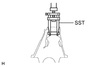
| 16. REMOVE REAR DRIVE PINION FRONT TAPERED ROLLER BEARING |
Using SST, remove the roller bearing (outer) from the carrier.
- SST
- 09308-00010
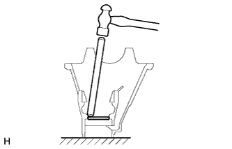
| 17. REMOVE DIFFERENTIAL OIL STORAGE RING |
Using a brass bar and hammer, tap out the oil storage ring from the carrier.
| 18. REMOVE REAR DRIVE PINION REAR TAPERED ROLLER BEARING |
Using a brass bar and hammer, tap out the rear tapered roller bearing (outer) from the carrier.
If the bearing is damaged during removal, replace it.
| 19. REMOVE DIFFERENTIAL RING GEAR |
Place matchmarks on the ring gear and differential case.
Text in Illustration*1
| Matchmark
|
Using a screwdriver and hammer, pry out the staked portions of the lock plates.
Remove the 10 ring gear set bolts and 5 lock plates.
Using a plastic-faced hammer, tap on the ring gear to separate it from the differential case.
| 20. INSPECT DIFFERENTIAL CASE ASSEMBLY RUNOUT |
If the ring gear runout is within the specified value (refer to the "Inspect Runout of Differential Ring Gear" procedure above), skip this step.Install the rear differential case bearings (outer) to the differential case.
Install the differential case to the differential carrier.
Install the 2 adjusting nuts.
Install the 2 bearing caps to the differential carrier with the 4 bolts.
- Torque:
- 85 N*m{867 kgf*cm, 63 ft.*lbf}
Inspect the differential case runout.
- Maximum runout:
- 0.07 mm (0.00276 in.)
Remove the 4 bolts and 2 bearing caps.
Remove the 2 adjusting nuts.
Remove the differential case.
Remove the rear differential case bearings (outer).
| 21. REMOVE REAR DIFFERENTIAL CASE BEARING |
Using SST, remove the 2 rear differential case bearings (inner) from the differential case.
- SST
- 09950-40011(09951-04020,09952-04010,09953-04030,09954-04010,09955-04061,09957-04010,09958-04011)
09950-60010(09951-00360)
- HINT:
- Do not remove the case bearings when not replacing the differential case.
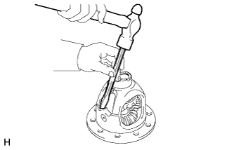
| 22. DISASSEMBLE DIFFERENTIAL CASE |
Using a chisel and hammer, unstake the differential case.
Using a pin punch and hammer, tap out the straight pin.
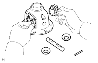
Remove the following parts from the differential case.
- (1) Pinion gear (2 pieces)
- (2) Pinion gear thrust washer (2 pieces)
- (3) Pinion shaft
- (4) Side gear (2 pieces)
- (5) Side gear thrust washer (2 pieces)
| 23. INSPECT DIFFERENTIAL GEAR KIT |
Check that the differential pinion and differential gear are not damaged.
- If the differential pinion or differential side gear is damaged, replace the differential gear kit.
| 24. INSPECT DIFFERENTIAL CASE |
Check that the differential case is not damaged.
- If the differential case is damaged, replace it.