Front Drive Shaft Assembly -- Reassembly |
- HINT:
- Use the same procedures for the RH side and LH side.
- The procedures listed below are for the LH side.
- A bolt without a torque specification is shown in the standard bolt chart (Toyota Fortuner RM00000118W017X.html).
| 1. INSTALL FRONT AXLE HUB DUST SEAL |
 |
Using a screwdriver and hammer, tap in a new dust seal.
- NOTICE:
- Do not damage the dust seal.
| 2. INSTALL FRONT DRIVE SHAFT DUST COVER |
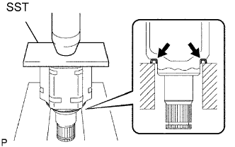 |
Using SST and a press, press in a new dust cover.
- SST
- 09527-10011
| 3. INSTALL HOLE SNAP RING |
Install a new snap ring.
| 4. INSTALL OUTBOARD JOINT BOOT |
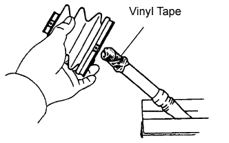 |
- HINT:
- Before installing the boots, wrap the spline of the drive shaft with vinyl tape to prevent the boots from being damaged.
Temporarily install a new outboard joint boot (with 2 boot clamps) to the drive shaft.
Pack the outboard joint and boot with grease from a boot kit.
- Standard grease capacity:
- 60 to 80 g (2.2 to 2.8 oz.)
| 5. INSTALL FRONT AXLE OUTBOARD JOINT BOOT CLAMP |
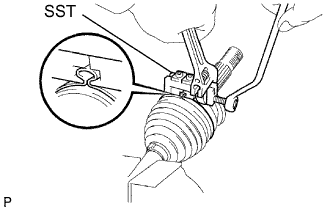 |
Mount the drive shaft in a soft vise.
Secure a new outboard joint large boot clamp onto the boot.
Place SST onto the clamp.
- SST
- 09521-24010
Tighten SST so that the boot clamp is pinched as shown in the illustration.
- NOTICE:
- Do not overtighten SST.
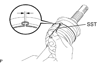
Using SST, adjust the clearance of the clamp.
- SST
- 09240-00020
- Standard clearance:
- 0.8 mm (0.0314 in.) or less
For the outboard joint small boot clamp, use the same procedures described above.
| 6. INSTALL INBOARD JOINT BOOT |
Install a new inboard joint boot to the outboard joint shaft.
| 7. INSTALL INBOARD JOINT |
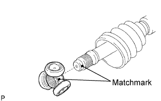 |
Align the matchmarks of the tripod and outboard joint.
- HINT:
- Place the beveled side of the tripod axial spline toward the outboard joint.
Using a brass bar and hammer, tap the tripod onto the outboard joint.
- NOTICE:
- Do not tap the rollers.
Using a snap ring expander, install a new snap ring.
Pack the inboard joint and boot with grease from a boot kit.
- Standard grease capacity:
- 121 to 141 g (4.3 to 4.9 oz.)
Align the matchmarks of the inboard joint and outboard joint.
Install the inboard joint to the outboard joint.
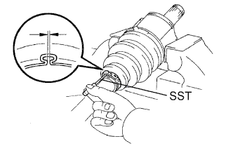
| 8. INSTALL FRONT AXLE INBOARD JOINT BOOT CLAMP |
 |
Using pliers, squeeze together the hooks of a new large clamp and install the large clamp.
Secure a new small boot clamp onto the boot.
Place SST onto the small boot clamp.
- SST
- 09521-24010
Tighten SST so that the small boot clamp is pinched as shown in the illustration.
- NOTICE:
- Do not overtighten SST.
 |
Using SST, adjust the clearance of the small boot clamp.
- SST
- 09240-00020
- Standard clearance:
- 1.0 to 4.0 mm (0.039 to 0.158 in.)
 |
| 9. INSPECT FRONT DRIVE SHAFT ASSEMBLY LH |
 |
*1: Check that there is no excessive play in the outboard joint.
*2: Check that the inboard joint slides smoothly in the thrust direction.
*3: Check that there is no excessive play in the radial direction of the inboard joint.
*4: Check the boots for damage.