Automatic Transmission Unit Disassembly
REMOVE TRANSMISSION CONTROL SHAFT LEVER LH
REMOVE PARK/NEUTRAL POSITION SWITCH ASSEMBLY
REMOVE OIL COOLER TUBE UNION
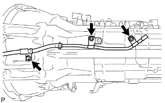
REMOVE SPEED SENSOR
REMOVE AUTOMATIC TRANSAXLE BREATHER TUBE
REMOVE AUTOMATIC TRANSMISSION HOUSING
REMOVE EXTENSION HOUSING SUB-ASSEMBLY
REMOVE EXTENSION HOUSING DUST DEFLECTOR
REMOVE AUTOMATIC TRANSMISSION EXTENSION HOUSING OIL SEAL
FIX AUTOMATIC TRANSMISSION CASE SUB-ASSEMBLY
REMOVE AUTOMATIC TRANSMISSION OIL PAN SUB-ASSEMBLY
INSPECT AUTOMATIC TRANSMISSION OIL PAN SUB-ASSEMBLY
REMOVE VALVE BODY OIL STRAINER ASSEMBLY
REMOVE TRANSMISSION WIRE
REMOVE TRANSMISSION VALVE BODY ASSEMBLY
REMOVE TRANSAXLE CASE GASKET
REMOVE BRAKE DRUM GASKET
REMOVE CHECK BALL BODY
REMOVE C-2 ACCUMULATOR PISTON
REMOVE B-3 ACCUMULATOR PISTON
REMOVE C-3 ACCUMULATOR PISTON
REMOVE C-1 ACCUMULATOR VALVE
REMOVE PARKING LOCK PAWL BRACKET
REMOVE PARKING LOCK ROD SUB-ASSEMBLY
REMOVE PARKING LOCK PAWL SHAFT
REMOVE MANUAL VALVE LEVER SUB-ASSEMBLY
REMOVE MANUAL VALVE LEVER SHAFT OIL SEAL
REMOVE OIL PUMP ASSEMBLY
REMOVE CLUTCH DRUM AND INPUT SHAFT ASSEMBLY
INSPECT 1-WAY NO. 2 CLUTCH ASSEMBLY
REMOVE 1-WAY NO. 2 CLUTCH ASSEMBLY
REMOVE NO. 3 BRAKE SNAP RING
REMOVE NO. 3 BRAKE DISC
INSPECT NO. 3 BRAKE DISC
REMOVE 2ND BRAKE PISTON HOLE SNAP RING
REMOVE 1-WAY CLUTCH ASSEMBLY
REMOVE 2ND BRAKE CYLINDER
REMOVE 2ND BRAKE PISTON
INSPECT NO. 3 BRAKE PISTON RETURN SPRING SUB-ASSEMBLY
REMOVE FRONT PLANETARY GEAR ASSEMBLY
INSPECT FRONT PLANETARY GEAR ASSEMBLY
INSPECT 1-WAY CLUTCH ASSEMBLY
REMOVE FRONT PLANETARY RING GEAR
REMOVE CENTER PLANETARY RING GEAR
REMOVE NO. 1 BRAKE DISC
INSPECT NO. 1 BRAKE DISC
REMOVE BRAKE PISTON RETURN SPRING SNAP RING
REMOVE BRAKE PISTON RETURN SPRING SUB-ASSEMBLY
INSPECT BRAKE PISTON RETURN SPRING SUB-ASSEMBLY
REMOVE NO. 1 BRAKE PISTON
REMOVE NO. 2 BRAKE DISC
INSPECT NO. 2 BRAKE DISC
INSPECT NO.2 BRAKE PISTON RETURN SPRING SUB-ASSEMBLY
REMOVE NO. 2 BRAKE PISTON
REMOVE CENTER PLANETARY GEAR ASSEMBLY
INSPECT CENTER PLANETARY GEAR ASSEMBLY
REMOVE INTERMEDIATE SHAFT
INSPECT NO. 3 1-WAY CLUTCH ASSEMBLY
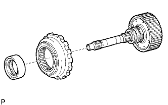
REMOVE NO. 3 1-WAY CLUTCH ASSEMBLY
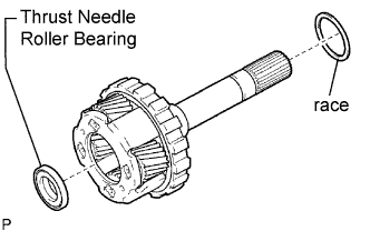
REMOVE REAR PLANETARY RING GEAR FLANGE SUB-ASSEMBLY
INSPECT REAR PLANETARY RING GEAR FLANGE SUB-ASSEMBLY
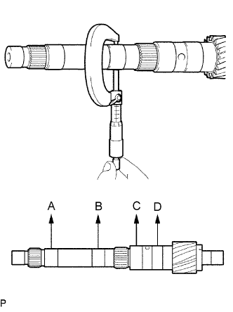
INSPECT INTERMEDIATE SHAFT
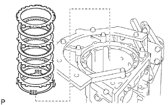
REMOVE BRAKE PLATE STOPPER SPRING
REMOVE NO. 4 BRAKE DISC
INSPECT NO. 4 BRAKE DISC
REMOVE REAR PLANETARY GEAR ASSEMBLY
INSPECT REAR PLANETARY GEAR ASSEMBLY
REMOVE 1ST AND REVERSE BRAKE RETURN SPRING SUB-ASSEMBLY
INSPECT 1ST AND REVERSE BRAKE RETURN SPRING SUB-ASSEMBLY
REMOVE 1ST AND REVERSE BRAKE PISTON
REMOVE BRAKE REACTION SLEEVE
REMOVE NO. 4 BRAKE PISTON
Automatic Transmission Unit -- Disassembly |
| 1. REMOVE TRANSMISSION CONTROL SHAFT LEVER LH |
Remove the nut, washer and control shaft lever LH.
| 2. REMOVE PARK/NEUTRAL POSITION SWITCH ASSEMBLY |
Using a screwdriver, pry out the lock washer.
Remove the nut, lock washer and bolt.
Remove the park/neutral position switch.
- HINT:
- Make sure that the manual valve lever shaft has not been rotated prior to installing the park/neutral position switch as the detent spring may become detached from the manual valve lever shaft.
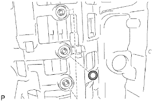
| 3. REMOVE OIL COOLER TUBE UNION |
Remove the 2 oil cooler tube unions.
Remove the O-ring from the oil cooler tube union.
Remove the 2 bolts and 2 sensors.
Remove the O-ring from each sensor.
| 5. REMOVE AUTOMATIC TRANSAXLE BREATHER TUBE |
Remove the 3 bolts.
Remove the breather tube.
Remove the O-ring from each tube.
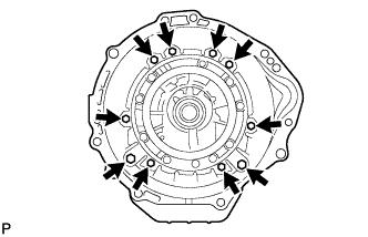
| 6. REMOVE AUTOMATIC TRANSMISSION HOUSING |
Remove the 10 bolts.
Remove the transmission housing.
| 7. REMOVE EXTENSION HOUSING SUB-ASSEMBLY |
Remove the 6 bolts.
Remove the extension housing assembly.
- HINT:
- Use a brass bar and hammer to remove the extension housing assembly.
Remove the gasket from the extension housing assembly.
Using a snap ring expander, remove the snap ring.
Remove the thrust needle roller bearing and 2 bearing races.
| 8. REMOVE EXTENSION HOUSING DUST DEFLECTOR |
Using a brass bar and hammer, remove the extension housing dust deflector.
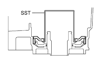
| 9. REMOVE AUTOMATIC TRANSMISSION EXTENSION HOUSING OIL SEAL |
Using SST, tap out the oil seal.
- SST
- 09308-00010
| 10. FIX AUTOMATIC TRANSMISSION CASE SUB-ASSEMBLY |
Install the transmission case on the overhaul attachment.
| 11. REMOVE AUTOMATIC TRANSMISSION OIL PAN SUB-ASSEMBLY |
- NOTICE:
- Do not turn the transmission over as this will contaminate the valve body with foreign matter on the bottom of the pan.
Remove the drain plug and 20 bolts.
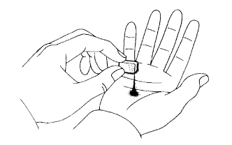
| 12. INSPECT AUTOMATIC TRANSMISSION OIL PAN SUB-ASSEMBLY |
Remove the magnets, and use them to collect steel particles.
Carefully look at the foreign matter and particles in the pan and on the magnets to anticipate the type of wear you will find in the transmission.
- Steel (magnetic): bearing, gear and clutch plate wear
- Brass (non-magnetic): bush wear
| 13. REMOVE VALVE BODY OIL STRAINER ASSEMBLY |
Turn over the transmission.
Remove the 4 bolts holding the valve body oil strainer assembly to the valve body.
Remove the O-ring form the valve body oil strainer assembly.
| 14. REMOVE TRANSMISSION WIRE |
Remove the ATF temperature sensor.
Remove the bolt and clamp.
Disconnect the 7 connectors from the shift solenoid valves.
Remove the bolt from the case.
Pull the transmission wire out of the transmission case.
Remove the O-ring from the transmission wire.
| 15. REMOVE TRANSMISSION VALVE BODY ASSEMBLY |
Remove the 19 bolts.
Remove the valve body assembly.
| 16. REMOVE TRANSAXLE CASE GASKET |
Remove the 3 transaxle case gaskets.
| 17. REMOVE BRAKE DRUM GASKET |
Remove the 3 brake drum gaskets.
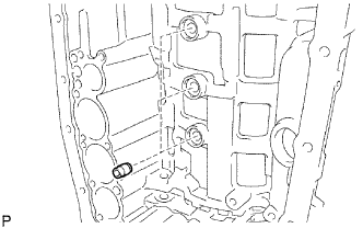
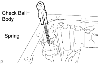
| 18. REMOVE CHECK BALL BODY |
Remove the check ball body and spring.
| 19. REMOVE C-2 ACCUMULATOR PISTON |
Applying compressed air to the oil hole, and remove the C2 accumulator piston and spring.
Remove the 2 O-rings from the piston.
- NOTICE:
- Be careful as the C-3 and B-3 accumulator piston may jump out.
| 20. REMOVE B-3 ACCUMULATOR PISTON |
Applying compressed air to the oil hole, and remove the C2 accumulator piston and spring.
Remove the 2 O-rings from the piston.
- NOTICE:
- Be careful as the C-3 accumulator piston may jump out.
| 21. REMOVE C-3 ACCUMULATOR PISTON |
Applying compressed air to the oil hole, and remove the B-3 accumulator piston and spring.
Remove the 2 O-rings from the piston.
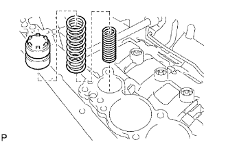
| 22. REMOVE C-1 ACCUMULATOR VALVE |
Remove the C-1 accumulator valve and 2 springs.
| 23. REMOVE PARKING LOCK PAWL BRACKET |
Remove the 3 bolts and parking lock pawl bracket.
| 24. REMOVE PARKING LOCK ROD SUB-ASSEMBLY |
Disconnect the parking lock rod from the manual valve lever.
| 25. REMOVE PARKING LOCK PAWL SHAFT |
Pull out the parking lock pawl shaft from the front side, and then remove the lock pawl and spring.
Remove the E-ring from the shaft.
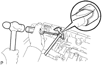
| 26. REMOVE MANUAL VALVE LEVER SUB-ASSEMBLY |
Using a hammer and screwdriver, cut off the spacer and remove it from the shaft.
Using a pin punch and hammer, tap out the spring pin.
- HINT:
- Slowly drive out the spring pin so that it does not fall into the transmission case.
Pull the manual valve lever shaft out through the case, and remove the manual valve lever.
| 27. REMOVE MANUAL VALVE LEVER SHAFT OIL SEAL |
Using a screwdriver, remove the 2 oil seals.
| 28. REMOVE OIL PUMP ASSEMBLY |
Remove the 10 bolts holding the oil pump from the transmission case.
Using SST, remove the oil pump.
- SST
- 09350-30020(09350-07020)
Remove the No. 1 thrust bearing race from the front oil pump.
| 29. REMOVE CLUTCH DRUM AND INPUT SHAFT ASSEMBLY |
Remove the clutch drum and input shaft drum assembly from the transmission case.
Remove the clutch drum thrust washer and thrust needle roller bearing.
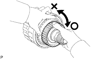
| 30. INSPECT 1-WAY NO. 2 CLUTCH ASSEMBLY |
Hold the reverse clutch hub and turn the No. 2 1-way clutch assembly
Check that the No. 2 1-way clutch assembly turns freely clockwise and locks when turned counterclockwise.
| 31. REMOVE 1-WAY NO. 2 CLUTCH ASSEMBLY |
Remove the No. 2 1-way clutch assembly and No. 2 clutch drum thrust washer from the clutch drum and input shaft assembly.
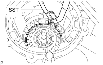
| 32. REMOVE NO. 3 BRAKE SNAP RING |
Using a screwdriver, remove the No. 3 brake snap ring from the case.
| 33. REMOVE NO. 3 BRAKE DISC |
Remove the flange and cushion plate the 4 discs and the 4 plates from the case.
| 34. INSPECT NO. 3 BRAKE DISC |
Replace all discs if one of the following problems is present: 1) a disc, plate or flange is worn or burnt, 2) the lining of a disc is peeled off or discolored, or 3) grooves or printed numbers have even a little bit of damage.
- NOTICE:
- Before assembling new discs, soak them in ATF for at least 15 minutes.
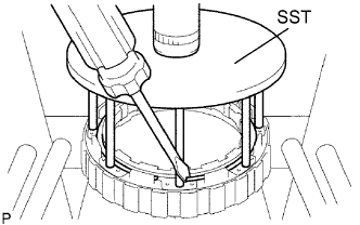
| 35. REMOVE 2ND BRAKE PISTON HOLE SNAP RING |
Using SST, remove the snap ring.
- SST
- 09350-30020(09350-07060)
| 36. REMOVE 1-WAY CLUTCH ASSEMBLY |
Remove the 1-way clutch assembly and the No. 1 planetary carrier thrust washer from the case.
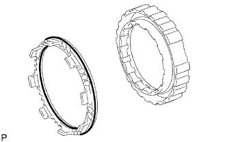
| 37. REMOVE 2ND BRAKE CYLINDER |
Remove the 2nd brake cylinder from the case.
| 38. REMOVE 2ND BRAKE PISTON |
Using SST, a press and screwdriver, remove the snap ring.
- SST
- 09351-40010
Hold the 2nd brake piston and apply compressed air (392 kPa, 4.0 kgf/cm2, 57 psi) to the brake cylinder to remove the 2nd brake piston.
Remove the 2 O-rings from the 2nd brake piston.
| 39. INSPECT NO. 3 BRAKE PISTON RETURN SPRING SUB-ASSEMBLY |
Using a vernier caliper, measure the free length of the spring together with the spring seat.
- Standard free length:
- 15.72 mm (0.6189 in.)
| 40. REMOVE FRONT PLANETARY GEAR ASSEMBLY |
Using a feeler gauge, measure the front planetary pinion gear thrust clearance.
- Standard clearance:
- 0.2 to 0.60 mm (0.008 to 0.0236 in.)
- Maximum clearance:
- 0.65 mm (0.0256 in.)
- If the clearance is greater than the maximum, replace the front planetary gear assembly.
Using a dial indicator, measure the inside diameter of the front planetary gear bushing.
- Maximum inside diameter:
- 57.48 mm (2.2630 in.)
- If the inside diameter is greater than the maximum, replace the front planetary gear.
| 41. INSPECT FRONT PLANETARY GEAR ASSEMBLY |
Using a feeler gauge, measure the front planetary pinion gear thrust clearance.
- Standard clearance:
- 0.2 to 0.60 mm (0.008 to 0.0236 in.)
- Maximum clearance:
- 0.65 mm (0.0256 in.)
- If the clearance is greater than the maximum, replace the front planetary gear assembly.
Using a dial indicator, measure the inside diameter of the front planetary gear bushing.
- Maximum inside diameter:
- 57.48 mm (2.2630 in.)
- If the inside diameter is greater than the maximum, replace the front planetary gear.
| 42. INSPECT 1-WAY CLUTCH ASSEMBLY |
Install the 1-way clutch assembly to the 1-way clutch inner race.
Hold the 1-way clutch inner race and turn the 1-way clutch assembly.
Check that the 1-way clutch assembly turns freely counterclockwise and locks when turned clockwise.
Remove the 1-way clutch assembly from the 1-way clutch inner race.
| 43. REMOVE FRONT PLANETARY RING GEAR |
Remove the front planetary ring gear and bearing from the transmission case.
| 44. REMOVE CENTER PLANETARY RING GEAR |
Using a screwdriver, remove the snap ring.
Remove the center planetary ring gear and front planetary ring gear flange from the front planetary ring gear.
| 45. REMOVE NO. 1 BRAKE DISC |
Remove the flange, 3 discs and 3 plates from the case.
| 46. INSPECT NO. 1 BRAKE DISC |
Replace all discs if one of the following problems is present: 1) a disc, plate or flange is worn or burnt, 2) the lining of a disc is peeled off or discolored, or 3) grooves or printed numbers have even a little bit of damage.
- NOTICE:
- Before assembling new discs, soak them in ATF for at least 15 minutes.
| 47. REMOVE BRAKE PISTON RETURN SPRING SNAP RING |
Using a screwdriver, remove the brake piston return spring snap ring from the case.
| 48. REMOVE BRAKE PISTON RETURN SPRING SUB-ASSEMBLY |
Remove the brake piston return spring and No. 1 brake piston with the No. 1 brake cylinder from the transmission case.
| 49. INSPECT BRAKE PISTON RETURN SPRING SUB-ASSEMBLY |
Using a vernier caliper, measure the free length of the spring together with the spring seat.
- Standard free length:
- 17.05 mm (0.6712 in.)
| 50. REMOVE NO. 1 BRAKE PISTON |
Hold the brake piston No. 1 and apply compressed air (392 kPa, 4 kgf/cm2, 57 psi) to the transmission case to remove the No. 1 brake piston.
- HINT:
- If the piston does not pop out with compressed air, lift the piston out with needle-nose pliers.
Remove the 2 O-rings from the No. 1 brake piston.
| 51. REMOVE NO. 2 BRAKE DISC |
Using a screwdriver, remove the snap ring from the case.
Remove the flange, the brake piston return spring, the 3 discs and the 3 plates from the case.
| 52. INSPECT NO. 2 BRAKE DISC |
Replace all discs if one of the following problems is present: 1) a disc, plate or flange is worn or burnt, 2) the lining of a disc is peeled off or discolored, or 3) grooves or printed numbers have even a little bit of damage.
- NOTICE:
- Before assembling new discs, soak them in ATF for at least 15 minutes.
| 53. INSPECT NO.2 BRAKE PISTON RETURN SPRING SUB-ASSEMBLY |
Using a vernier caliper, measure the free length of the spring together with the spring seat.
- Standard free length:
- 17.45 mm (0.6870 in.)
| 54. REMOVE NO. 2 BRAKE PISTON |
Hold the No. 2 brake piston and apply compressed air (392 kPa, 4 kgf/cm2, 57 psi) to the transmission case to remove the No. 2 brake piston.
- HINT:
- If the piston does not pop out with compressed air, lift the piston out with needle-nose pliers.
Remove the 2 O-rings from the No. 2 brake piston.
| 55. REMOVE CENTER PLANETARY GEAR ASSEMBLY |
Remove the center planetary gear assembly, the planetary sun gear and the No. 4 thrust bearing race from the case.
| 56. INSPECT CENTER PLANETARY GEAR ASSEMBLY |
Using a feeler gauge, measure the center planetary gear pinion thrust clearance.
- Standard clearance:
- 0.12 to 0.68 mm (0.0047 to 0.0268 in.)
- Maximum clearance:
- 0.73 mm (0.0287 in.)
- If the clearance is greater than the maximum, replace the center planetary gear assembly.
| 57. REMOVE INTERMEDIATE SHAFT |
Using a screwdriver, remove the snap ring from the case.
Remove the intermediate shaft with the No. 3 1- way clutch assembly from the case.
| 58. INSPECT NO. 3 1-WAY CLUTCH ASSEMBLY |
Hold the rear planetary ring gear flange sub-assembly turn the 1-way clutch assembly.
Check that the 1-way clutch assembly turns freely counterclockwise and locks when turned clockwise.
| 59. REMOVE NO. 3 1-WAY CLUTCH ASSEMBLY |
Remove the No. 3 1-way clutch assembly and the 1 way clutch inner race from the intermediate shaft.
| 60. REMOVE REAR PLANETARY RING GEAR FLANGE SUB-ASSEMBLY |
Remove the No. 8 thrust bearing race thrust needle roller bearing, the No. 7 thrust bearing race and the planetary ring gear flange from the intermediate shaft.
| 61. INSPECT REAR PLANETARY RING GEAR FLANGE SUB-ASSEMBLY |
Using a caliper gauge, measure the inside diameter of the rear planetary ring gear bushing.
- Maximum inside diameter:
- 32.18 mm (1.2669 in.)
- If the inside diameter is greater than the maximum, replace the rear planetary ring gear.
| 62. INSPECT INTERMEDIATE SHAFT |
Using a dial indicator, check the intermediate shaft runout.
- Maximum runout:
- 0.08 mm (0.0031 in.)
- NOTICE:
- If the bend exceeds the specification, replace the intermediate shaft with a new one.
Using a micrometer, check the outer diameter of the intermediate shaft positions shown in the diagram.
- Standard diameter:
- A:
- 25.96 to 25.98 mm (1.0220 to 1.0228 in.)
- B:
- 25.96 to 25.98 mm (1.0220 to 1.0228 in.)
- C:
- 32.06 to 32.08 mm (1.2622 to 1.2630 in.)
- D:
- 32.06 to 32.08 mm (1.2622 to 1.2630 in.)
- Minimum diameter:
- A:
- 25.91 mm (1.0201 in.)
- B:
- 25.91 mm (1.0201in.)
- C:
- 32.01 mm (1.2602 in.)
- D:
- 32.01 mm (1.2602 in.)
- NOTICE:
- If the outer diameter is outside the standard or less than the minimum, replace the intermediate shaft with the new one.
| 63. REMOVE BRAKE PLATE STOPPER SPRING |
Remove the brake plate stopper spring from the case.
| 64. REMOVE NO. 4 BRAKE DISC |
Remove the 7 plates, the 8 discs and the 2 flanges from the case.
| 65. INSPECT NO. 4 BRAKE DISC |
Replace all discs if one of the following problems is present: 1) a disc, plate or flange is worn or burnt, 2) the lining of a disc is peeled off or discolored, or 3) grooves or printed numbers have even a little bit of damage.
- NOTICE:
- Before assembling new discs, soak them in ATF for at least 15 minutes.
| 66. REMOVE REAR PLANETARY GEAR ASSEMBLY |
Remove the rear planetary gear assembly from the case.
Remove the thrust bearing race No. 9 and the thrust needle roller bearing from the rear planetary gear assembly.
Remove the thrust needle roller bearing from the case.
| 67. INSPECT REAR PLANETARY GEAR ASSEMBLY |
Using a caliper gauge, measure the inside diameter of the rear planetary ring gear bushing.
- Maximum inside diameter:
- 32.18 mm (1.2669 in.)
- If the inside diameter is greater than the maximum, replace the rear planetary ring gear.
| 68. REMOVE 1ST AND REVERSE BRAKE RETURN SPRING SUB-ASSEMBLY |
Place SST on the spring retainer and compress the brake return spring.
- SST
- 09350-30020(09350-07050)
Using SST, remove the snap ring and the brake return spring.
- SST
- 09350-30020(09350-07070)
| 69. INSPECT 1ST AND REVERSE BRAKE RETURN SPRING SUB-ASSEMBLY |
Using a vernier caliper, measure the free length of the spring together with the spring seat.
- Standard free length:
- 23.74 mm (0.9346 in.)
| 70. REMOVE 1ST AND REVERSE BRAKE PISTON |
Hold the No. 2 brake piston and apply compressed air (392 kPa, 4 kgf/cm2, 57 psi) to the transmission case to remove the No. 2 brake piston.
- HINT:
- If the piston does not pop out with compressed air, lift the piston out with needle-nose pliers.
Remove the O-ring from No. 2 brake piston.
| 71. REMOVE BRAKE REACTION SLEEVE |
Using SST, remove the reaction sleeve.
- SST
- 09350-30020(09350-07080)
Remove the O-ring from the reaction sleeve.
| 72. REMOVE NO. 4 BRAKE PISTON |
Using SST, remove the No. 4 brake piston.
- SST
- 09350-30020(09350-07090)
Remove the 2 O-rings from the No. 4 piston.