Dtc P0717/67 Input Speed Sensor Circuit No Signal
DESCRIPTION
MONITOR DESCRIPTION
WIRING DIAGRAM
INSPECTION PROCEDURE
CHECK SPEED SENSOR (INSTALLATION)
INSPECT SPEED SENSOR (NCO)
CHECK WIRE HARNESS (SPEED SENSOR (NCO) - TCM)
DTC P0717/67 Input Speed Sensor Circuit No Signal |
DESCRIPTION
The speed sensor (NCO) detects the rotation speed of the O/D input shaft from the rotation speed of the O/D direct clutch drum. Its construction is the same as that of the speed sensor (SP2).By comparing the speed sensor (NCO) signal with the speed sensor (SP2) signal, the TCM detects the shift timing of the gears and controls the engine torque and hydraulic pressure according to various conditions. As a result, the gears shift smoothly.DTC Code
| DTC Detection Condition
| Trouble Area
|
P0717/67
| - All conditions below are detected for 5 sec. or more
(2 trip detection logic):
- Gear changes not being performed
- Gear position: 1st, 2nd or 3rd
- Transmission input shaft rpm: less than 300 rpm
- Transmission output shaft rpm: 500 rpm or more
- Park/neutral position switch: OFF
- Shift solenoid valve S1, S2, and SL, and vehicle speed sensor (SPD1) are operating normally
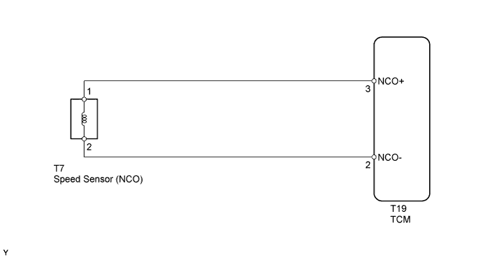
| - Open or short in speed sensor (NCO) circuit
- Speed sensor (NCO)
- TCM
|
MONITOR DESCRIPTION
The speed sensor (NCO) detects the transmission input shaft speed. The TCM determines the gear shift timing based on a comparison of the speed sensor (NCO) (input shaft speed) with the output speed sensor (output shaft speed).When the output shaft speed is higher than the expected value and the input shaft speed is less than 300 rpm while the vehicle is running with the shift lever on D, the TCM will conclude that there is a malfunction in the speed sensor (NCO). The TCM will illuminate the MIL and set the DTC.
WIRING DIAGRAM
INSPECTION PROCEDURE
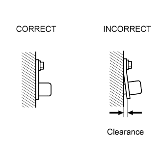
| 1.CHECK SPEED SENSOR (INSTALLATION) |
Check the speed sensor installation.
- OK:
- Installation bolt is tightened properly and there is no clearance between sensor and transmission case.
| | SECURELY INSTALL SPEED SENSOR OR REPLACE SPEED SENSOR |
|
|
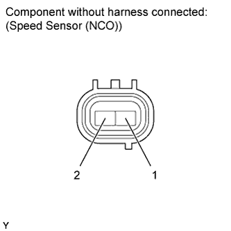
| 2.INSPECT SPEED SENSOR (NCO) |
Disconnect the T7 sensor connector from the transmission.
Measure the resistance of the sensor.
- Standard Resistance:
Tester Connection
| Condition
| Specified Condition
|
1 - 2
| 20°C (68°F)
| 560 to 680 Ω
|
| | REPLACE SPEED SENSOR (NCO) |
|
|
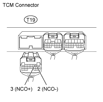
| 3.CHECK WIRE HARNESS (SPEED SENSOR (NCO) - TCM) |
Disconnect the T19 TCM connector.
Measure the resistance of the wire harness side connector.
- Standard Resistance:
Tester Connection
| Condition
| Specified Condition
|
T19-3 (NCO+) - T19-2 (NCO-)
| 20°C (68°F)
| 560 to 680 Ω
|
T19-3 (NCO+) - Body ground
| Always
| 10 kΩ or higher
|
T19-2 (NCO-) - Body ground
| Always
| 10 kΩ or higher
|
| | REPAIR OR REPLACE HARNESS OR CONNECTOR |
|
|