Direct Clutch -- Reassembly |
| 1. INSTALL DIRECT CLUTCH PISTON |
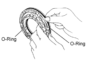 |
Coat 2 new O-rings with ATF, and install them in the direct clutch piston.
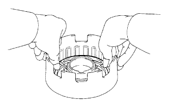
Be careful not to damage the O-rings, and press in the direct clutch piston into the clutch drum with both hands.
 |
| 2. INSTALL DIRECT CLUTCH RETURN SPRING |
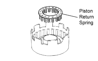 |
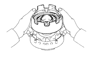
Place SST on the spring retainer, and compress the return spring with a press.
- SST
- 09350-30020(09350-07040)
 |
Using SST, install the snap ring.
- SST
- 09350-30020(09350-07070)
- NOTICE:
- Be sure the end gap of the snap ring is not aligned with the spring retainer claw.
| 3. INSTALL DIRECT CLUTCH FLANGE |
 |
Install the cushion plate.
Install the 4 plates and 4 discs.
- Install in order:
- P - D - P - D - P - D - P - D
- HINT:
- P = Plate
- D = Disc
Install the flange with the flat end facing downward.
Using a screwdriver, install the snap ring.
- NOTICE:
- Be sure the end gap of the snap ring is not aligned with the cutout portion of the direct clutch drum.
 |
| 4. INSPECT PACK CLEARANCE OF DIRECT CLUTCH |
 |
Place the direct clutch assembly onto the O/D support assembly.
Using SST and a dial indicator, measure the direct clutch pack clearance while applying and releasing compressed air (186 to 206 kPa (1.9 to 2.1 kgf/cm2, 27 to 30 psi)).
- SST
- 09350-30020(09350-06120)
- Pack clearance:
- 0.40 to 0.70 mm (0.016 to 0.028 in.)
- HINT:
- If the pack clearance is still not as specified, select another flange.
- There are 8 different flange thicknesses.
- Flange Thickness:
No. Specified Condition No. Specified Condition 53 3.3 mm (0.130 in.) 57 3.7 mm (0.146 in.) 54 3.4 mm (0.134 in.) 58 3.8 mm (0.150 in.) 55 3.5 mm (0.138 in.) 60 4.0 mm (0.157 in.) 56 3.6 mm (0.142 in.) 62 4.2 mm (0.165 in.)
 |