Automatic Transmission System Tcm Power Source Circuit
DESCRIPTION
WIRING DIAGRAM
INSPECTION PROCEDURE
INSPECT FUSE (IGN)
INSPECT IGNITION SWITCH
CHECK WIRE HARNESS (TCM - BODY GROUND)
CHECK TCM (TCM - BATTERY)
AUTOMATIC TRANSMISSION SYSTEM - TCM Power Source Circuit |
DESCRIPTION
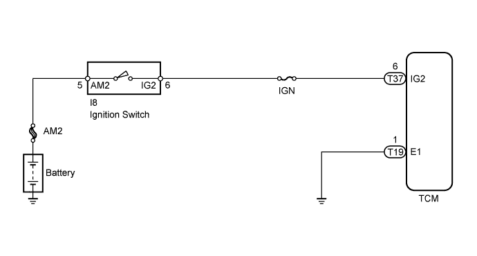
When the ignition switch is turned ON, battery voltage is applied to terminal IG2 of the TCM.
WIRING DIAGRAM
INSPECTION PROCEDURE
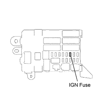
Remove the IGN fuse from the instrument panel junction block.
Measure the resistance of the fuse.
- Standard Resistance:
- Below 1 Ω
| 2.INSPECT IGNITION SWITCH |
Disconnect the I8 ignition switch connector.
Measure the resistance of the ignition switch.
- Standard Resistance:
Tester Connection
| Switch Condition
| Specified Condition
|
5 (AM2) - 6 (IG2)
| OFF
| 10 kΩ or higher
|
5 (AM2) - 6 (IG2)
| ON
| Below 1 Ω
|
| 3.CHECK WIRE HARNESS (TCM - BODY GROUND) |
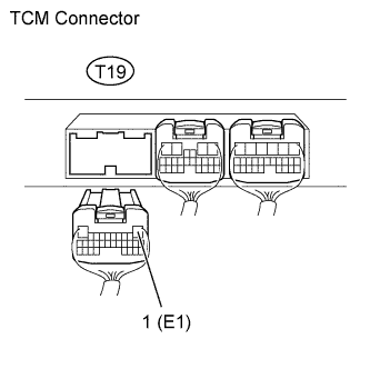
Disconnect the T19 TCM connector.
Measure the resistance of the wire harness side connector.
- Standard Resistance:
Tester Connection
| Condition
| Specified Condition
|
T19-1 (E1) - Body ground
| Always
| Below 1 Ω
|
| | REPAIR OR REPLACE HARNESS OR CONNECTOR |
|
|
| 4.CHECK TCM (TCM - BATTERY) |
Turn the ignition switch to ON.
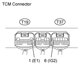
Measure the voltage of the TCM connectors.
- Standard Voltage:
Tester Connection
| Switch Condition
| Specified Condition
|
T37-6 (IG2) - T19-1 (E1)
| Ignition switch ON
| 11 to 14 V
|
| | REPAIR OR REPLACE HARNESS OR CONNECTOR |
|
|