Oil Pump -- Removal |
| 1. DISCHARGE FUEL SYSTEM PRESSURE |
Connect the intelligent tester to the DLC3.
Turn the ignition switch ON.
- NOTICE:
- Do not start the engine.
Push the intelligent tester main switch ON.
To perform the Active Test, enter the following menus: Powertrain / Engine and ECT / Active Test / Control the Fuel Pump / Speed.
 |
Check the fuel pump operation.
Check for pressure in the fuel inlet tube from the fuel line. Check that the sound of fuel flowing in the fuel tank can be heard.
If there is no sound, check the integration relay, fuel pump, ECM and wiring connector.
Check for fuel leaks.
Check that there are no fuel leaks after performing maintenance anywhere on the system.
If there are fuel leaks, repair or replace the leaking parts.
| 2. DISCONNECT CABLE FROM NEGATIVE BATTERY TERMINAL |
- CAUTION:
- Wait at least 90 seconds after disconnecting the cable from the negative (-) battery terminal to prevent airbag and seat belt pretensioner activation.
- NOTICE:
- When disconnecting the cable, systems need to be initialized after the cable is reconnected.
| 3. REMOVE ENGINE ASSEMBLY |
Remove the engine from the vehicle (Toyota Fortuner RM000000YMH003X.html).
| 4. REMOVE DRIVE PLATE AND RING GEAR ASSEMBLY (for Automatic Transmission) |
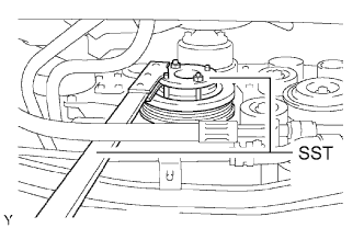
Using SST, hold the crankshaft.
- SST
- 09213-54015(91651-60855)
09330-00021
 |
Remove the 8 bolts, rear spacer, drive plate and front spacer.
- NOTICE:
- Do not reuse the bolts.
 |
| 5. REMOVE FLYWHEEL (for Manual Transmission) |
Using SST, hold the crankshaft.
- SST
- 09213-54015(91651-60855)
09330-00021
|
Remove the 8 bolts and flywheel.
- NOTICE:
- Do not reuse the bolts.
 |
| 6. INSTALL ENGINE ASSEMBLY TO STAND |
| 7. REMOVE OIL DIPSTICK GUIDE |
Remove the oil dipstick gauge.
Remove the bolt and oil dipstick guide.
Remove the O-ring from the oil dipstick guide.
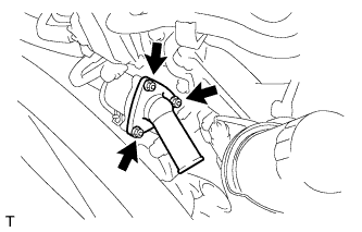
| 8. REMOVE WATER INLET |
Remove the 3 nuts, water inlet housing with thermostat and gasket.
 |
| 9. REMOVE GENERATOR |
 |
Disconnect the terminal cap.
Remove the nut and generator wire.
Disconnect the generator connector.
Remove the 2 bolts, adjusting bar and generator.
| 10. REMOVE V-RIBBED BELT TENSIONER |
Remove the 5 bolts and V-ribbed belt tensioner.
 |
| 11. REMOVE NO. 2 IDLER PULLEY |
- NOTICE:
- Use the same procedure for both No. 2 idler pulleys.
w/ Idler Pulley Cover Plate:
Remove the bolt, No. 2 idler pulley cover plate, idler pulley and idler pulley cover plate.

w/o Idler Pulley Cover Plate:
Remove the bolt, No. 2 idler pulley cover plate and idler pulley.

for Integrated Type:
Remove the 2 bolts and 2 No. 2 idler pulleys.
 |
| 12. REMOVE NO. 1 IDLER PULLEY |
Remove the bolt and idler pulley.
| 13. REMOVE CRANKSHAFT PULLEY |
Turn the crankshaft pulley, and align its groove with timing mark 0 of the timing chain cover.
 |
Check that the timing marks of the camshaft timing gears are aligned with the timing marks of the bearing cap as shown in the illustration.
If not, turn the crankshaft 1 revolution (360°) and align the timing marks as described above.
 |
Using SST, hold the crankshaft pulley and loosen the pulley set bolt.
- SST
- 09213-54015(91651-60855)
09330-00021
 |
Using the pulley set bolt and SST, remove the crankshaft pulley.
- SST
- 09950-50013(09951-05010,09952-05010,09953-05020,09954-05030)
 |
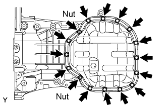
| 14. REMOVE NO. 2 OIL PAN |
Remove the 14 bolts and 2 nuts.
 |
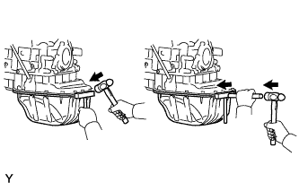
Insert the blade of an oil pan seal cutter between the oil pan and No. 2 oil pan, cut through the applied sealer and remove the No. 2 oil pan.
- NOTICE:
- Be careful not to damage the contact surfaces of the No. 1 oil pan and No. 2 oil pan.
- Be careful not to damage the No. 2 oil pan flange.
 |
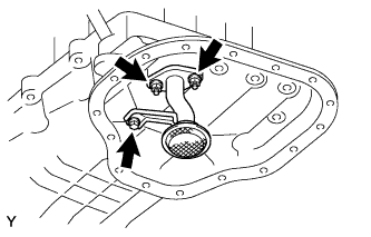
| 15. REMOVE OIL STRAINER |
Remove the bolt, 2 nuts, oil strainer and gasket.
 |
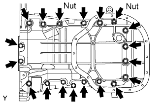
| 16. REMOVE NO. 1 OIL PAN |
Remove the 17 bolts and 2 nuts.
 |
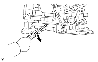
Using a screwdriver, remove the oil pan by prying between the oil pan and cylinder block as shown in the illustration.
- NOTICE:
- Be careful not to damage the contact surfaces of the cylinder block and oil pan.
 |
Remove the O-ring from the oil pump.
| 17. REMOVE IGNITION COIL |
| 18. REMOVE CYLINDER HEAD COVER RH |
Remove the 10 bolts, 3 seal washers, 2 nuts, cylinder head cover and gasket.
 |
| 19. REMOVE CYLINDER HEAD COVER LH |
Remove the 10 bolts, 3 seal washers, 2 nuts, cylinder head cover and gasket.
 |
| 20. REMOVE CAMSHAFT TIMING OIL CONTROL VALVE |
Disconnect the 2 oil control valve connectors.
Remove the 2 bolts and 2 oil control valves.
| 21. REMOVE VVT SENSOR |
Disconnect the sensor connector.
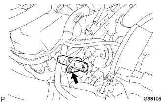 |
Remove the bolt and sensor.
| 22. REMOVE OIL FILTER BRACKET |
Remove the 3 bolts, 2 nuts, oil filter bracket and gasket.
| 23. REMOVE TIMING CHAIN COVER |
Remove the 24 bolts and 2 nuts.
 |
Remove the timing chain cover by prying between the timing chain cover and cylinder head or cylinder block with a screwdriver.
- NOTICE:
- Be careful not to damage the contact surfaces of the timing chain cover, cylinder block and cylinder head.
 |
Remove the O-ring from the LH cylinder head.
| 24. REMOVE TIMING CHAIN COVER OIL SEAL |
Using a screwdriver, pry out the oil seal.
- NOTICE:
- Be careful not to damage the oil pump body.
- HINT:
- Tape the screwdriver tip before use.
Using SST and a hammer, tap in a new oil seal until its surface is flush with the timing chain cover edge.
- SST
- 09226-10010
 |
Apply MP grease to the lip of the oil seal.