Fuel System System Diagram
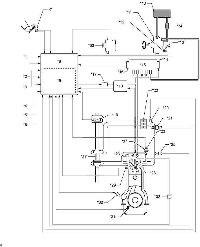
FUEL FLOW DIAGRAM
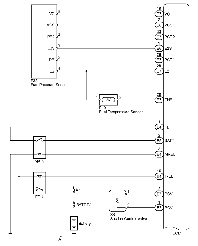
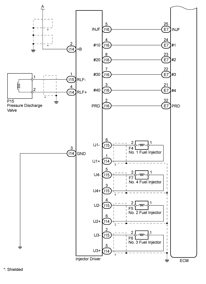
FUEL SYSTEM WIRING DIAGRAM
Fuel System -- System Diagram |
Text in Illustration*1
| Ignition Switch Signal
| *2
| Starter Signal
|
*3
| Vehicle Speed Signal
| *4
| DLC3
|
*5
| Battery Voltage
| *6
| Other Signal
|
*7
| Accelerator Position Sensor
| *8
| ECM
|
*9
| Atmospheric Pressure Sensor
| *10
| Fuel Tank
|
*11
| Fuel Supply Pump
| *12
| Fuel Temperature Sensor
|
*13
| Suction Control Valve
| *14
| Pressure Discharge Valve
|
*15
| Common Rail
| *16
| Fuel Pressure Sensor
|
*17
| EDU Relay
| *18
| Injector Driver
|
*19
| Mass Air Flow Meter
| *20
| Intake Air Temperature Sensor
|
*21
| Diesel Throttle Body
| *22
| Intercooler
|
*23
| EGR Valve Position Sensor
| *24
| EGR Valve
|
*25
| Manifold Absolute Pressure Sensor
| *26
| Fuel Injector
|
*27
| Turbocharger
| *28
| Glow Plug
|
*29
| Engine Coolant Temperature Sensor
| *30
| Camshaft Position Sensor
|
*31
| Crankshaft Position Sensor
| *32
| Glow Relay
|
*33
| Generator
| *34
| Fuel Cooler
|
| FUEL SYSTEM WIRING DIAGRAM |
By storing fuel at a high pressure, the common rail system provides the pressure necessary for fuel injection.