Engine Unit -- Reassembly |
- HINT:
- Thoroughly clean all parts to be assembled.
- Before installing the parts, apply new engine oil to all sliding and rotating surfaces.
- Replace all gaskets, O-rings and oil seals with new parts.
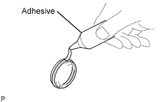
| 1. INSTALL TIGHT PLUG |
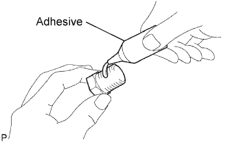
Apply adhesive to a new tight plug.
- Adhesive:
- Toyota Genuine Adhesive 1324, Three Bond 1324 or equivalent
- NOTICE:
- Do not start the engine for 1 hour after the installation.
 |
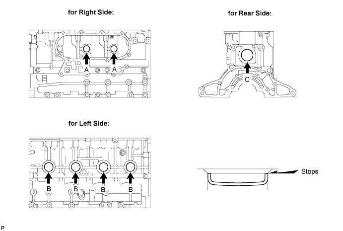
Using SST and a hammer, tap in the 2 tight plugs A.
- SST
- 09950-60010(09951-00250)
09950-70010(09951-07100)
Using SST and a hammer, tap in the 4 tight plugs B.
- SST
- 09950-60010(09951-00350)
09950-70010(09951-07100)
Using SST and a hammer, tap in tight plug C.
- SST
- 09950-60010(09951-00500)
09950-70010(09951-07100)
| 2. INSTALL STUD BOLT |
- NOTICE:
- If the stud bolt is deformed or the threads are damaged, replace it.
Install the stud bolts as shown in the illustration.

- Torque:
- 15 N*m{150 kgf*cm, 11 ft.*lbf}
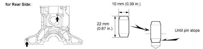
| 3. INSTALL STRAIGHT PIN |
Install the straight pins as shown in the illustration.
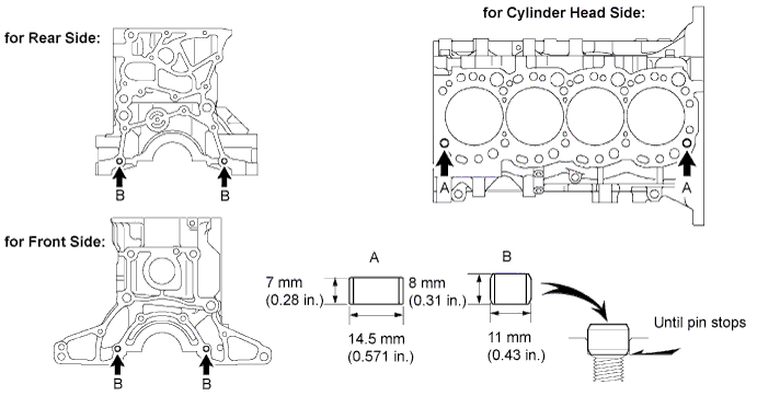
| 4. INSTALL RING PIN |
Install the ring pins as shown in the illustration.
| 5. INSTALL NO. 1 TAPER SCREW PLUG |
Apply adhesive to 2 or 3 threads.
- Adhesive:
- Toyota Genuine Adhesive 1324, Three Bond 1324 or equivalent
 |
Install the screw plug.
- Torque:
- 20 N*m{204 kgf*cm, 15 ft.*lbf}
| 6. INSTALL CYLINDER BLOCK WATER DRAIN COCK SUB-ASSEMBLY |
Apply adhesive to 2 or 3 threads.
- Adhesive:
- Toyota Genuine Adhesive 1324, Three Bond 1324 or equivalent
 |
Install the water drain cock.
- Torque:
- 57 N*m{581 kgf*cm, 42 ft.*lbf}
- HINT:
- After applying the specified torque, rotate the drain union clockwise until its drain port is facing downward.
- The drain port may be set within 45° of either side of the prescribed position.
 |
| 7. INSTALL CYLINDER BLOCK OIL ORIFICE |
Using a 6 mm hexagon wrench, install the oil orifice.
- Torque:
- 11 N*m{112 kgf*cm, 8 ft.*lbf}
| 8. INSTALL NO. 1 OIL NOZZLE SUB-ASSEMBLY |
Align the pin of the oil nozzle with the pin hole of the cylinder block.
 |
Install the 4 oil nozzles with the 4 check valves.
- Torque:
- 25.5 N*m{260 kgf*cm, 19 ft.*lbf}
| 9. INSTALL PISTON SUB-ASSEMBLY |
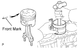
Assemble the piston and connecting rod.
Using snap ring pliers, install a new snap ring on one side of the piston pin hole.
Gradually heat the piston to approximately 60°C (140°F).
Coat the piston pin with engine oil.
Align the front marks of the piston and connecting rod, and push in the piston pin with your thumb.
Check the fitting condition between the piston and piston pin. Try to move the piston back and forth on the piston pin.
Using snap ring pliers, install a new snap ring on the other side of the piston pin hole.


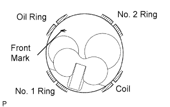
Install the piston rings.
Install the coil and oil ring by hand.
- HINT:
- Face the end gap of the oil ring in the opposite direction of the coil joint.
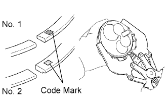
Using a piston ring expander, install the No. 1 and No. 2 piston rings with the code mark facing upward.
- Code mark:
Item Code Mark No. 1 piston ring 1N No. 2 piston ring 2N
Position the piston rings so that the ring ends are as shown in the illustration.
- NOTICE:
- Do not align the ring ends.

| 10. INSTALL CONNECTING ROD BEARING |
Align the bearing claw with the groove of the connecting rod or connecting rod cap.
 |
Install the bearings in the connecting rod and connecting rod cap.
| 11. INSTALL CRANKSHAFT BEARING |
- HINT:
- Upper bearings have an oil groove and oil hole; lower bearings do not.
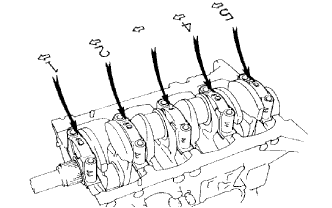
Align the bearing claw with the claw groove of the cylinder block, and push in the 5 upper bearings.
 |
Align the bearing claw with the claw groove of the crankshaft bearing cap, and push in the 5 lower bearings.
 |
| 12. INSTALL CRANKSHAFT THRUST WASHER SET |
Install the 2 thrust washers with the oil grooves facing outward as shown in the illustration.
 |
Install the 2 thrust washers to the No. 3 crankshaft bearing cap with the grooves facing outward as shown the illustration.
 |
| 13. INSTALL CRANKSHAFT |
Place the crankshaft on the cylinder block.
Install the 5 crankshaft bearing caps in their proper locations.
 |
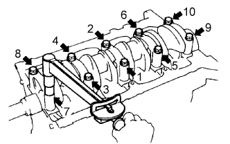
Install the crankshaft bearing cap bolts.
Apply a light coat of the engine oil to the threads and under the bolt heads of the crankshaft bearing caps.
Install and uniformly tighten the 10 bolts of the crankshaft bearing caps, in several steps, in the sequence shown in the illustration.
- Torque:
- 105 N*m{1,071 kgf*cm, 77 ft.*lbf}
Check that the crankshaft turns smoothly.
Check the crankshaft thrust clearance (Toyota Fortuner RM00000125A00CX_01_0107.html).
| 14. INSTALL PISTON AND CONNECTING ROD |
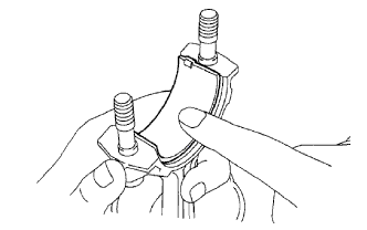
Cover the connecting rod bolts with a short piece of hose to protect the crankshaft and cylinder bore from damage.
 |
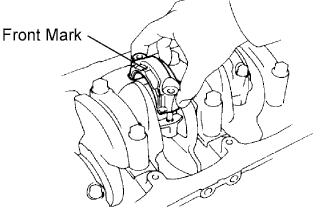
Using a piston ring compressor, push the correctly numbered piston and connecting rod into the cylinder with the front mark of the piston facing forward.
 |
Place the connecting rod cap on the connecting rod.
Match the numbered connecting rod cap with the connecting rod.
Install the connection rod cap with the front mark facing forward.
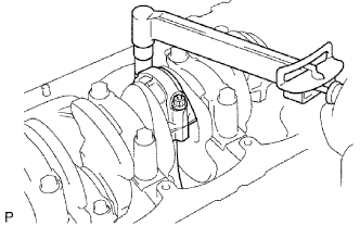
Install the connecting rod cap nuts.
If any connecting rod bolt is broken or deformed, replace it.- HINT:
- The connecting rod cap nuts are tightened in 2 progressive steps.
Apply a light of engine oil to the threads and under the heads of the connecting rod cap nuts.
Install and alternately tighten the nuts of the connecting rod cap in several passes.
- Torque:
- 54 N*m{551 kgf*cm, 40 ft.*lbf}
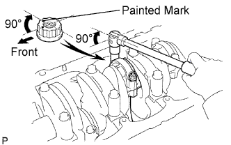
Mark the front of the connecting rod cap nuts with paint.
Retighten the connecting rod cap nuts 90° as shown.
Check that the painted marks are now at a 90° angle to the front.
Check that the crankshaft turns smoothly.
Check the connecting rod thrust clearance (Toyota Fortuner RM00000125A00CX_01_0103.html).
| 15. INSTALL ENGINE REAR OIL SEAL RETAINER |
Install a new gasket and the retainer with the 4 bolts.
- Torque:
- 13 N*m{133 kgf*cm, 10 ft.*lbf}
| 16. INSTALL TIMING BELT CASE SUB-ASSEMBLY |
Place a new gasket on the cylinder block.
Install the timing belt case with the 5 bolts.
- Torque:
- 22.5 N*m{229 kgf*cm, 17 ft.*lbf}
 |
| 17. INSTALL OIL STRAINER SUB-ASSEMBLY |
Install a new gasket and oil strainer with the 2 bolts and 2 nuts.
- Torque:
- 21 N*m{214 kgf*cm, 15 ft.*lbf}for nut
- 18 N*m{184 kgf*cm, 13 ft.*lbf}for bolt
| 18. INSTALL OIL PAN SUB-ASSEMBLY |
Using a gasket scraper, remove all the old seal packing material from the installation surface of the oil pan and cylinder block.
- Thoroughly clean all components to remove all the loose material.
- Using a non-residue solvent, clean both of the sealing surfaces.
- NOTICE:
- Do not use a solvent which will affect the painted surfaces.
- Do not apply any oil on the contact surfaces of the oil pan and cylinder block.
- Thoroughly clean all components to remove all the loose material.
Remove any old seal packing material and do not drop any oil on the contact surfaces of the oil pan and cylinder block.
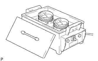
Apply seal packing to the oil pan as shown in the illustration.
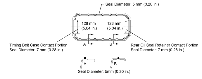
- Seal packing:
- Toyota Genuine Seal Packing Black, Three Bond 1207B or equivalent
- Standard seal diameter:
- 5 mm (0.20 in.)
- 7 mm (0.28 in.) for timing belt case contact portion
- 7 mm (0.28 in.) for rear oil seal retainer contact portion
- HINT:
- Do not apply an excessive amount to the surface, especially near the oil passages.
- Parts must be assembled within 5 minutes of application. Otherwise the material must be removed and reapplied.
- After application, immediately remove the nozzle from the tube and reinstall the cap.
Install the oil pan with the 16 bolts and 2 nuts. Uniformly tighten the bolts and nuts in several steps.
- Torque:
- 18 N*m{184 kgf*cm, 13 ft.*lbf}
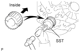
| 19. INSTALL CRANKSHAFT TIMING PULLEY |
Align the pulley set key with the key groove of the timing pulley.
Using SST and a hammer, tap in the timing pulley, facing the flange side inward.
- SST
- 09223-46011
 |
| 20. INSTALL WATER PUMP ASSEMBLY |
Install a new gasket, the water pump and tension spring bracket with the 6 bolts.
- Torque:
- 23 N*m{235 kgf*cm, 17 ft.*lbf}
 |
| 21. INSTALL NO. 2 TIMING BELT IDLER SUB-ASSEMBLY |
Install the spacer and No. 2 timing belt idler with the bolt.
- Torque:
- 33 N*m{337 kgf*cm, 24 ft.*lbf}
Check that the No. 2 timing belt idler moves smoothly.
| 22. INSTALL NO. 1 TIMING BELT IDLER SUB-ASSEMBLY |
Temporarily install the No. 1 timing belt idler with the 3 bolts labeled A, B and C.
 |
Tighten the bolt C.
- Torque:
- 19 N*m{194 kgf*cm, 14 ft.*lbf}
- HINT:
The bolt lengths for bolts A, B and C as follows.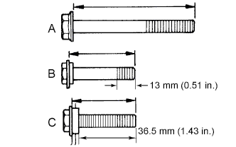
- A:
- 76.5 mm (3.012 in.)
- B:
- 42.9 mm (1.689 in.)
- C:
- 41.3 mm (1.626 in.)
- Bolt C is combined with the No. 1 timing belt idler.
| 23. INSTALL CYLINDER HEAD |
Install the cylinder head (Toyota Fortuner RM00000128D003X.html).