Dtc 32 (1) Injection Pump System Malfunction
DESCRIPTION
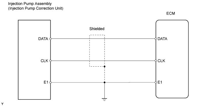
WIRING DIAGRAM
INSPECTION PROCEDURE
CHECK HARNESS AND CONNECTOR (ECM - INJECTION PUMP CORRECTION UNIT)
REPLACE INJECTION PUMP ASSEMBLY
CHECK DTC OUTPUT (DTC 32 (1) IS OUTPUT AGAIN)
DTC 32 (1) Injection Pump System Malfunction |
DESCRIPTION
To compensate for the change in injection volume and injection timing caused by the variance in the injection pump itself, a correction is made by using the data that is stored in the ROM in the fuel pump correction unit.DTC No.
| DTC Detection Condition
| Trouble Area
|
32 (1)
| - When ignition switch is turned ON, or when ECM determines if there is error in RAM of ECM, ECM conducts single communication. If one of following conditions occurs in single communication, ECM conducts another communication. While ECM is conducting communication, ECM detects DTC 32 (1) if (a) occurs 20 times continuously, (b) occurs 20 times continuously, or (c) occurs 2 times continuously.
- (a) There was communication error when receiving data.
- (b) Data sent from injection pump correction unit does not match data received in ECM.
- (c) Data received from pump ROM is not input for 1024 msec.
- HINT:
- Even when determining if process is completed normally, if undefined code is found while checking identification code of data received, ECM conducts communication again. If undefined code occurs 20 times continuously, ECM detects DTC 32 (1).
| - Open or short in injection pump correction unit circuit
- Injection pump correction unit
- ECM
|
WIRING DIAGRAM
INSPECTION PROCEDURE
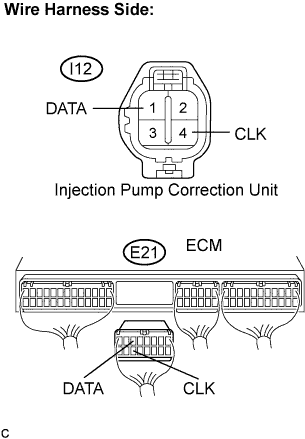
| 1.CHECK HARNESS AND CONNECTOR (ECM - INJECTION PUMP CORRECTION UNIT) |
Disconnect the I12 injection pump correction unit connector.
Disconnect the E21 ECM connector.
Measure the resistance of the wire harness side connectors.
- Standard resistance:
Tester Connection
| Specified Condition
|
I12-1 (DATA) - E21-6 (DATA)
| Below 1 Ω
|
I12-4 (CLK) - E21-14 (CLK)
| Below 1 Ω
|
I12-1 (DATA) or E21-6 (DATA) - Body ground
| 10 kΩ or higher
|
I12-4 (CLK) or E21-14 (CLK) - Body ground
| 10 kΩ or higher
|
| | REPAIR OR REPLACE HARNESS OR CONNECTOR |
|
|
| 2.REPLACE INJECTION PUMP ASSEMBLY |
| 3.CHECK DTC OUTPUT (DTC 32 (1) IS OUTPUT AGAIN) |
Clear the DTC (Toyota Fortuner RM000000VR600DX.html).
Turn the ignition switch ON.
Check the DTC (Toyota Fortuner RM000000VR600DX.html).
- Result:
Display (DTC output)
| Proceed to
|
DTC 32 (1) is output again
| A
|
No DTC output
| B
|