Ecd System Vc Output Circuit
DESCRIPTION
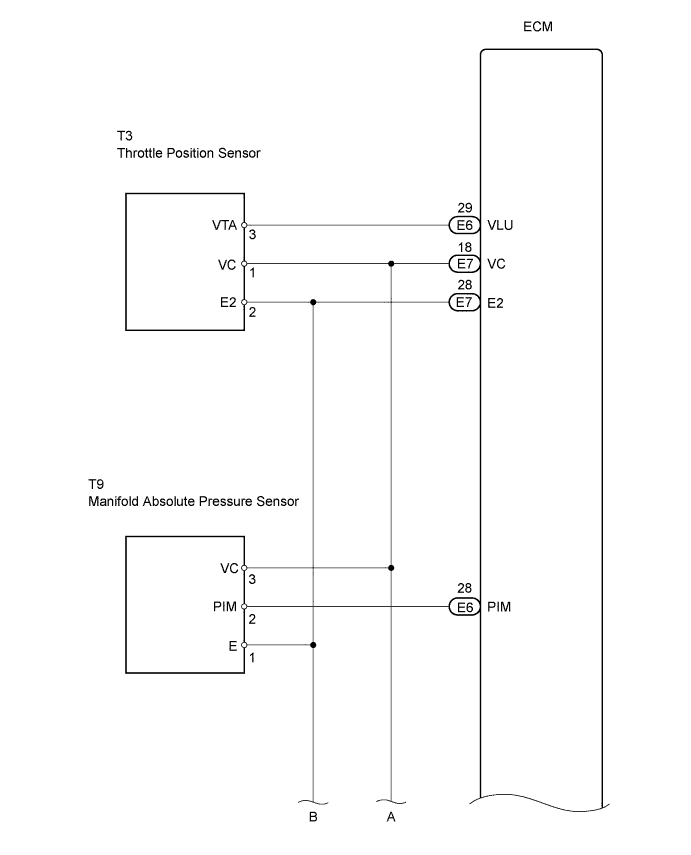
WIRING DIAGRAM
INSPECTION PROCEDURE
CHECK MIL
CHECK CONNECTION BETWEEN INTELLIGENT TESTER AND ECM
CHECK ECM (VC VOLTAGE)
CHECK MIL (THROTTLE POSITION SENSOR)
CHECK MIL (MANIFOLD ABSOLUTE PRESSURE SENSOR)
CHECK MIL (ACCELERATOR PEDAL POSITION SENSOR)
CHECK MIL (FUEL PRESSURE SENSOR)
CHECK HARNESS AND CONNECTOR (ECM - BODY GROUND)
ECD SYSTEM - VC Output Circuit |
DESCRIPTION
The VC voltage (5 V) is generated in the ECM. The voltage is used to supply power to the throttle body assembly, EGR valve position sensor, turbo pressure sensor, accelerator position sensor and fuel pressure sensor.
WIRING DIAGRAM
INSPECTION PROCEDURE
- NOTICE:
- After replacing the ECM, the new ECM needs registration (Toyota Fortuner RM0000012XK030X.html) and initialization (See page 8Toyota Fortuner RM0000012X2005X.html).
Check that the Malfunction Indicator Lamp (MIL) lights up when turning the ignition switch ON.
- OK:
- MIL lights up
| 2.CHECK CONNECTION BETWEEN INTELLIGENT TESTER AND ECM |
Connect the intelligent tester to the DLC3.
Turn the ignition switch ON and tester ON.
Check the communication between the intelligent tester and ECM.
- Result:
Condition
| Proceed to
|
Communication is not possible
| A
|
Communication is possible
| B
|
Turn the ignition switch ON.
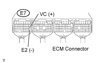
Measure the voltage of the ECM connector.
- Result:
Tester Connection
| Specified Condition
|
VC (E7-18) - E2 (E7-28)
| Voltage is not 5 V
|
| 4.CHECK MIL (THROTTLE POSITION SENSOR) |
Disconnect the T3 throttle position sensor connector.
Turn the ignition switch ON.
Check the MIL.
- Result:
Condition
| Proceed to
|
MIL does not illuminate
| A
|
MIL illuminates
| B
|
Reconnect the throttle position sensor connector.
| 5.CHECK MIL (MANIFOLD ABSOLUTE PRESSURE SENSOR) |
Disconnect the T9 manifold absolute pressure sensor connector.
Turn the ignition switch ON.
Check the MIL.
- Result:
Condition
| Proceed to
|
MIL does not illuminate
| A
|
MIL illuminates
| B
|
Reconnect the manifold absolute pressure sensor connector.
| | REPLACE MANIFOLD ABSOLUTE PRESSURE SENSOR |
|
|
| 6.CHECK MIL (ACCELERATOR PEDAL POSITION SENSOR) |
Disconnect the A22 accelerator pedal position sensor connector.
Turn the ignition switch ON.
Check the MIL.
- Result:
Condition
| Proceed to
|
MIL does not illuminate
| A
|
MIL illuminates
| B
|
Reconnect the accelerator position sensor connector.
| 7.CHECK MIL (FUEL PRESSURE SENSOR) |
Disconnect the F32 fuel pressure sensor connector.
Turn the ignition switch ON.
Check the MIL.
- Result:
Condition
| Proceed to
|
MIL does not illuminate
| A
|
MIL illuminates
| B
|
Reconnect the fuel pressure sensor connector.
| 8.CHECK HARNESS AND CONNECTOR (ECM - BODY GROUND) |
Disconnect the T3 throttle position sensor connector.
Disconnect the T9 manifold absolute pressure sensor connector.
Disconnect the F32 fuel pressure sensor connector.
Disconnect the A22 accelerator pedal position sensor connector.
Disconnect the E7 ECM connector.
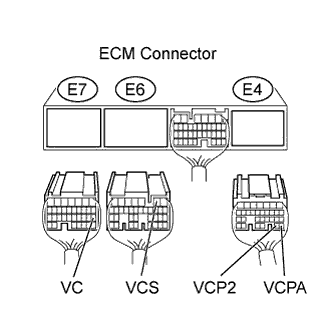
Measure the resistance of the wire harness connector.
- Standard resistance (Check for short):
Tester Connection
| Specified Condition
|
VC (E7-18) - Body ground
| 10 kΩ or higher
|
VCS (E6-2) - Body ground
|
VCPA (E4-26) - Body ground
|
VCP2 (E4-27) - Body ground
|
Reconnect the throttle position sensor connector.
Reconnect the manifold absolute pressure sensor connector.
Reconnect the fuel pressure sensor connector.
Reconnect the accelerator pedal position sensor connector.
Reconnect the ECM connector.
| | REPAIR OR REPLACE HARNESS OR CONNECTOR |
|
|