Dtc P0234/34 Turbocharger / Supercharger Overboost Condition
DESCRIPTION
WIRING DIAGRAM
INSPECTION PROCEDURE
CHECK OTHER DTC OUTPUT (IN ADDITION TO DTC P0234/34, P0299/34 AND /OR P1251/34)
READ VALUE USING INTELLIGENT TESTER (MAP)
CHECK EXHAUST SYSTEM
CHECK AIR CLEANER FILTER
CHECK INTAKE SYSTEM
INSPECT TURBOCHARGER SUB-ASSEMBLY
CHECK ECM (VNTI VOLTAGE)
CHECK ECM (VNTO VOLTAGE)
CHECK EGR VALVE ASSEMBLY
INSPECT INTAKE AIR TEMPERATURE SENSOR
DTC P0234/34 Turbocharger / Supercharger Overboost Condition |
DTC P0299/34 Turbocharger / Supercharger Underboost |
DTC P1251/34 Step Motor for Turbocharger Control Circuit (Intermittent) |
DESCRIPTION
- HINT:
- *: Only for 1KD-FTV
Refer to DTC P0045/34 (Toyota Fortuner RM000000YGU003X_01.html). DTC No.
| DTC Detection Condition
| Trouble Area
|
P0234/34
| When turbocharger boost pressure continues to be higher than ECM's target boost pressure.
(1 trip detection logic)
| - Turbocharger sub-assembly
- Turbo motor driver
- Manifold absolute pressure sensor
- MAF meter
- EGR valve stuck closed
- Exhaust system and intake system are modified or clogged
- ECM
|
P0299/34
| When turbocharger boost pressure continues to be lower than ECM's target boost pressure.
(1 trip detection logic)
| - Turbocharger sub-assembly
- Turbo motor driver
- Manifold absolute pressure sensor
- MAF meter
- EGR valve stuck open
- Manifold absolute pressure sensor (hose disconnected)
- Exhaust system and intake system are modified or clogged
- ECM
|
P1251/34
| When turbocharger boost pressure is higher than boost pressure for a short time in which there was possibility of engine damage.
(1 trip detection logic)
| - Turbocharger sub-assembly
- Turbo motor driver
- Manifold absolute pressure sensor
- MAF meter
- EGR valve assembly
- Exhaust system and intake system are modified or clogged
- ECM
|
WIRING DIAGRAM
Refer to DTC P0045/34 (Toyota Fortuner RM000000YGU003X_03.html).
INSPECTION PROCEDURE
- HINT:
- Read freeze frame data using the intelligent tester. Freeze frame data records the engine conditions when a malfunction is detected. When troubleshooting, freeze frame data can help determine if the vehicle was running or stopped, if the engine was warmed up or not, and other data from the time the malfunction occurred.
- NOTICE:
- If the ECM is replaced, the new ECM needs initialization (Toyota Fortuner RM0000012X2005X.html).
| 1.CHECK OTHER DTC OUTPUT (IN ADDITION TO DTC P0234/34, P0299/34 AND /OR P1251/34) |
Connect the intelligent tester to the DLC3.
Turn the ignition switch ON and turn the intelligent tester ON.
Enter the following menus: Powertrain / Engine / DTC.
Read the DTCs.
- Result:
Display (DTC Output)
| Proceed to
|
P0234/34, P0299/34 and/or P1251/34
| A
|
P0234/34, P0299/34 and/or P1251/34 and other DTCs
| B
|
| 2.READ VALUE USING INTELLIGENT TESTER (MAP) |
Connect the intelligent tester to the DLC3.
Start the engine and warm it up. Turn the intelligent tester ON.
Enter the following menu: Powertrain / Engine / Data List / MAP.
- Standard value (reference):
Item
| Engine Speed*
| Specified condition
|
MAP
| Ignition switch ON
| Same as atmospheric pressure
|
Idling
| 95 to 105 kPa
(713 to 788 mmHg, 28.1 to 31 in.Hg)
|
3,000 rpm (no engine load)
| 110 to 135 kPa
(825 to 1,012 mm Hg, 32.5 to 39.9 in.Hg)
|
- HINT:
- *: If no idling conditions are specified, the A/C switch and all accessory switches should be OFF with a fully warm engine.
| | REPLACE MANIFOLD ABSOLUTE PRESSURE SENSOR |
|
|
Turn the ignition switch ON.
Check the exhaust pipe for leaks.
- OK:
- Exhaust pipe has no leaks.
| | REPAIR OR REPLACE EXHAUST SYSTEM |
|
|
| 4.CHECK AIR CLEANER FILTER |
Check that the air cleaner filter is not clogged.
- OK:
- Air cleaner filter is not clogged.
| | REPLACE AIR CLEANER FILTER ELEMENT SUB-ASSEMBLY |
|
|
Disconnect the air cleaner hose.
Use a mirror to visually check the turbocharger for any mechanical problems.
When the engine is cold, check that the impeller of the turbocharger rotates smoothly, and perform a contact check to confirm whether there is any damage on it.
- OK:
- impeller of turbocharger rotates smoothly.
| | REPAIR OR REPLACE INTAKE SYSTEM |
|
|
| 6.INSPECT TURBOCHARGER SUB-ASSEMBLY |
Disconnect the air cleaner hose.
Use a mirror to visually check the turbocharger for any mechanical problems.
When the engine is cold, check that the impeller of the turbocharger rotates smoothly, and perform a contact check to confirm whether there is any damage on it.
- OK:
- Impeller of turbocharger rotates smoothly.
| | REPLACE TURBOCHARGER SUB-ASSEMBLY |
|
|
| 7.CHECK ECM (VNTI VOLTAGE) |
While idling the engine, check the waveform of the ECM connectors using an oscilloscope.
- OK:
Tester Connection
| Specified Condition
|
E7-17 (VNTI) - E6-7 (E1)
| Correct waveform is as shown
|
Tool Setting
| Condition
|
5 V/DIV., 20 msec./DIV.
| Idling with warm engine
|
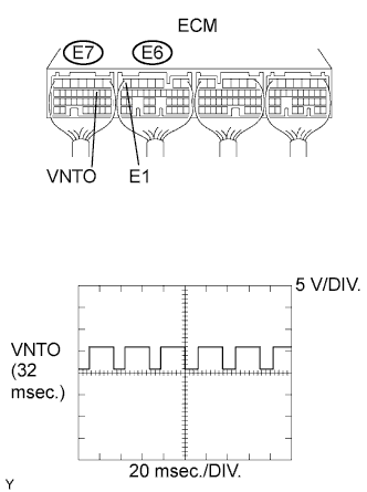
| 8.CHECK ECM (VNTO VOLTAGE) |
While idling the engine, check the waveform of the ECM connectors using an oscilloscope.
- OK:
Tester Connection
| Specified Condition
|
E7-10 (VNTO) - E6-7 (E1)
| Correct waveform is as shown
|
Tool Setting
| Condition
|
5 V/DIV., 20 msec./DIV.
| Idling with warm engine
|
| | REPLACE TURBO MOTOR DRIVER |
|
|
| 9.CHECK EGR VALVE ASSEMBLY |
| | REPLACE EGR VALVE ASSEMBLY |
|
|
| 10.INSPECT INTAKE AIR TEMPERATURE SENSOR |
Check the IAT sensor.
Remove the MAF meter.
Measure the resistance of the sensor.
- Standard resistance:
Tester Connection
| Condition
| Specified Condition
|
4 - 5
| -20°C (-4°F)
| 13.6 to 18.4 kΩ
|
20°C (68°F)
| 2.21 to 2.69 kΩ
|
60°C (140°F)
| 0.49 to 0.67 kΩ
|
| | REPLACE MASS AIR FLOW METER |
|
|